Introduction
Selecting a casting method for aluminum parts is both a technical and economic decision. Tighter tolerances and better surface finish almost always cost more, yet compromising on either creates problems downstream. For aluminum molds used in rotational molding, that tradeoff is especially unforgiving. A porous interior surface or inconsistent wall thickness doesn't just affect aesthetics—it ruins parts and shortens mold life.
Sand casting remains the dominant solution. According to Waupaca Foundry, green sand casting is the most widely used process for both ferrous and non-ferrous metals, with automated lines capable of exceeding 300 molds per hour. For aluminum specifically, its relatively low pour temperature and excellent fluidity make it a natural fit for this process.
This guide covers the full picture: how sand casting works, how to evaluate foundry sand, the tools involved, aluminum-specific process considerations, and how casting quality connects to rotational mold performance.
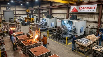
The guidance draws on 70 years of production experience from Rotocast Technologies' foundry in Akron, Ohio—grounded in what actually works on the floor, not textbook theory.
Key Takeaways
- Sand casting is the most widely used casting process globally; aluminum's low pour temperature (1,250–1,400°F versus steel's 2,850–2,950°F) makes it a natural fit for high-volume mold production
- Green sand molds are single-use, but the sand itself is reconditioned and reused across many pours
- Hydrogen porosity, oxide films, and shrinkage are manageable — each responds to specific, well-established process controls
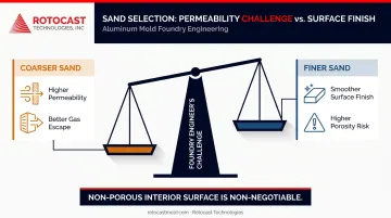
- A non-porous interior surface is non-negotiable for rotational molds — it directly determines part quality and cycle consistency
- Few North American foundries consistently meet the thin-wall, low-porosity standards rotomolding demands
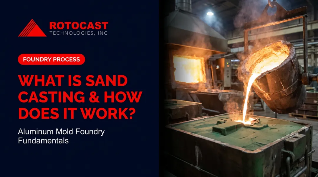
What Is Sand Casting and How Does It Work?
Sand casting forms a mold cavity in compacted sand using a pattern, fills the cavity with molten metal, and releases the solidified casting by breaking apart the mold. The American Foundry Society defines the cope as the top half of a horizontally parted mold and the drag as the bottom half. A gating system—comprising a sprue (the vertical entry channel), runners, and ingates—delivers molten metal into the cavity.
The Four Main Variants
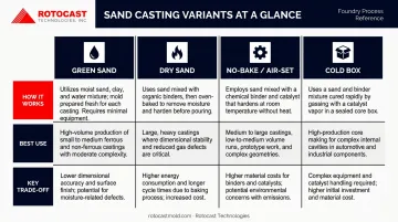
Not all sand casting is the same. The binder system determines speed, strength, moisture risk, and dimensional control:
| Variant | How It Works | Best Use |
|---|---|---|
| Green sand | Moist clay-bonded sand, used uncured | High-volume, cost-sensitive production |
| Dry sand | Tempered sand baked dry before use | Higher strength, lower moisture risk |
| No-bake / air-set | Resin-bonded sand cured at room temperature | Larger or more dimensionally demanding molds |
| Cold box | Sand hardened in box using amine-activated resin | High-productivity coremaking |
The choice of variant affects surface quality, cycle time, and suitability for aluminum. Green sand is the default for most production work; chemically bonded systems deliver tighter dimensional control and superior surface finish — critical factors when producing precision rotational molds.
Foundry Sand: Types, Composition, and What to Look For
Green Sand Composition
A typical green sand mixture contains high-quality silica sand bound with 5–10% bentonite clay, 2–5% water, and roughly 5% sea coal or other carbonaceous additives, per the Recycled Materials Resource Center. The base sand makes up the remainder—typically 75–85% of the mixture by volume.
Each component plays a distinct role:
- Bentonite provides the binding strength that holds the mold together under metal pressure
- Water activates the clay and controls green strength and flowability
- Sea coal creates a reducing atmosphere (low-oxygen environment) during pour, limiting surface oxidation
Base Sand Comparison
| Sand Type | Fusion Point | Thermal Behavior | Notes |
|---|---|---|---|
| Silica | >1,690°C | >4% expansion at 573°C | Most common; lowest cost |
| Olivine | ~1,400°C | Lower, more linear expansion | Silica-free; useful where silica risk is a concern |
| Chromite | ~2,180°C | High heat transfer | Specialty/additive for thermal control |
| Zircon | ~2,550°C | Low expansion, high conductivity | High cost; demanding surface/thermal cases |
Aluminum pours at 1,250–1,400°F, well below gray iron (2,300–2,600°F) or steel (2,850–2,950°F). That lower thermal demand gives aluminum foundries more flexibility in sand selection than ferrous shops have.
Silica's prevalence in that selection, though, comes with a non-negotiable requirement. OSHA sets a permissible exposure limit of 50 µg/m³ as an 8-hour TWA for respirable crystalline silica, with associated risks including silicosis, lung cancer, and COPD. Proper exposure controls apply regardless of pour temperature or application.
Key Sand Properties
Foundry engineers evaluate molding sand on several properties — each one a balance between competing demands:
- Refractoriness sets the ceiling: sand must withstand pour temperature without fusing to the casting surface
- Permeability controls gas escape during solidification; coarser grains help, but at a cost to surface quality
- Flowability determines how well sand compacts around complex pattern geometry without voids
- Cohesiveness, collapsibility, and green/dry strength govern how the mold holds its shape during pour — and releases the casting cleanly afterward
The permeability/surface finish trade-off is the most common tension in aluminum mold production. Rotational molds need smooth interior surfaces, which pushes toward finer sand—but finer sand traps gas more readily, increasing porosity risk.
Sand Recycling
The AFS estimates 6–10 million tons of foundry sand are generated annually. Roughly 2.6 million tons are beneficially reused — with the EPA recognizing pathways including manufactured soil, road subbase, Portland cement aggregate, and embankment fill.
Within the foundry itself, sand can be screened, reconditioned, and cycled across many pours. Clay activity diminishes over time, though, requiring fresh bentonite additions to restore bond strength.
Essential Foundry Tools and Equipment for Mold Making
Flasks and Structural Components
The molding flask (cope and drag sections) retains sand during ramming and establishes the mold's dimensional reference. Flask condition directly affects accuracy—worn pins, bent sides, or uneven parting surfaces create misalignment that shows up in the casting.
Metal flasks are preferred for production work; wood is acceptable for small-scale or emergency use. Complex parts with undercuts or significant height may require a cheek—an intermediate flask section between the cope and drag.
Hand Tools and Mold Finishing Equipment
The U.S. Navy Foundry Manual provides clear definitions for the core molder's toolkit:
- Riddle – sifts facing sand evenly over the pattern surface
- Rammer – compacts sand around the pattern and in lifts
- Strike bar – levels sand flush with the flask top
- Trowels and slickers – smooth flat surfaces, patch defects, and shape corners
- Vent wire – creates gas escape channels through the cope
- Draw spike / draw screw – raps the pattern to break adhesion, then pulls it cleanly
Supporting Hardware: Gaggers, Chaplets, and Chills
Three accessories play critical roles in mold integrity and casting quality:
- Gaggers are internal metal supports that prevent overhanging sand masses in the cope from collapsing under their own weight
- Chaplets are small metal spacers that hold cores in position within the mold cavity
- Chills are metal inserts that accelerate local solidification, controlling grain structure and preventing shrinkage in heavy sections
The Foundry Manual flags a direct contamination risk: rusty or damp chills and chaplets cause blows because rust reacts with molten metal to release gas, and moisture turns to steam. Keep them dry, clean, and oxide-free before closing every mold.
The Sand Casting Process: Step-by-Step for Aluminum Molds
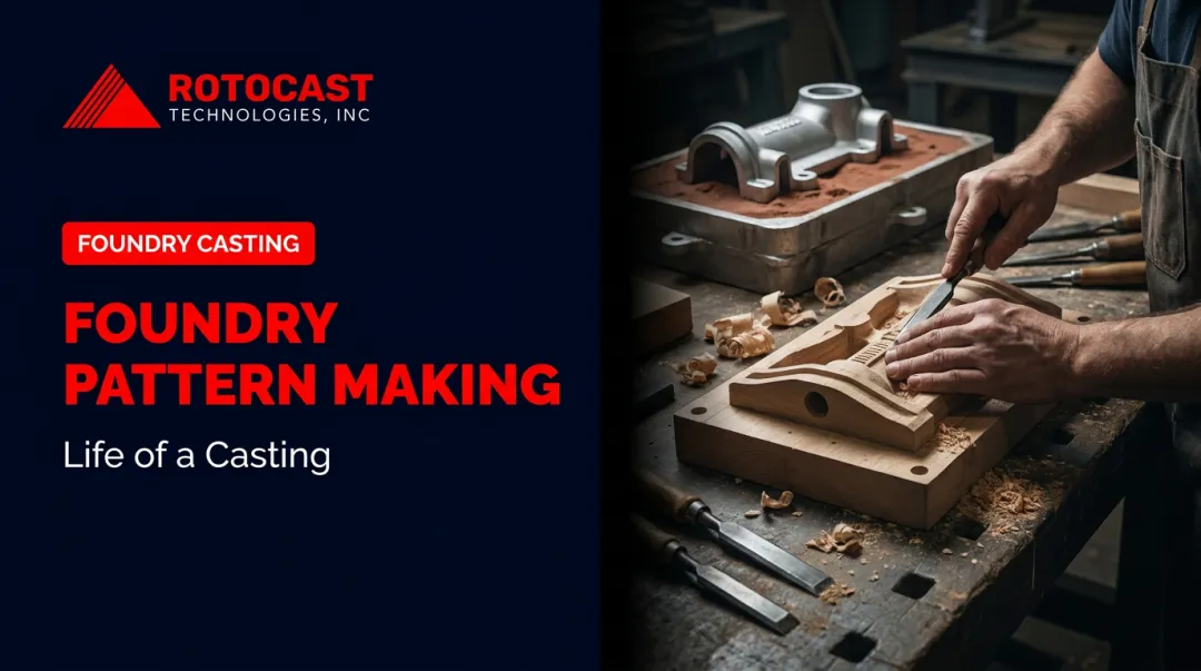
Step 1 – Pattern Creation and Flask Setup
The pattern must be oversized to account for metal contraction during solidification. For aluminum, a typical shrinkage allowance is approximately 5/32 in/ft (roughly 1.3%)—verify final values against the specific alloy and casting geometry before committing the pattern.
Key pattern requirements:
- Draft angles of 0.0625 in/ft or 1–3° on vertical surfaces to allow clean withdrawal
- Pattern material chosen for production volume (wood for prototypes and short runs; metal for high-volume production)
- Flask sizing that leaves adequate space around the pattern for the gating system, risers, and cope wall strength
Step 2 – Ramming the Drag and Cope
The sequence matters:
- Place the drag upside down on a ram-up board
- Riddle facing sand over the pattern; hand-pack pockets and corners first
- Add backing sand in lifts, ramming uniformly to consistent density
- Strike off excess sand; place the bottom board and roll the flask
- Set the cope on the drag; apply parting compound
- Set sprue and riser forms; riddle and ram the cope in lifts
- Vent the cope with a vent wire through the full depth
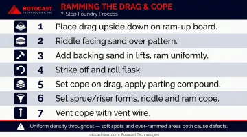
Uniform ramming density is critical throughout. Soft spots collapse under metal pressure; over-rammed areas reduce permeability and trap gas—either defect can kill the casting.
Step 3 – Drawing the Pattern and Finishing the Cavity
Rap the pattern lightly with a draw spike before withdrawal—this breaks adhesion without enlarging the cavity. Use draw screws or eye bolts for controlled, straight extraction on larger patterns.
After drawing:
- Inspect both cope and drag for torn surfaces or sharp projections
- Smooth the pour gate and basin
- Remove any loose sand that could erode into the metal stream
- Set cores into their core prints; verify seating before closing the mold
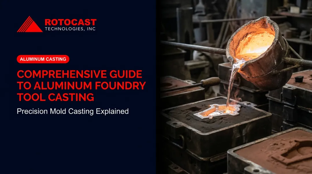
Step 4 – Pouring, Cooling, and Shakeout
Pour technique directly affects casting quality. Keep the ladle lip as close to the basin as possible to minimize metal fall height, fill the basin quickly, and maintain a full basin throughout the pour.
Key pouring controls:
- Skim slag before the pour and again during if needed
- Watch riser fill as confirmation the mold cavity is full
- Time shakeout carefully—too early risks distortion; too late wastes cycle time
Once shaken out, the sand stream is screened to remove metal fragments and lumps before reconditioning.
Step 5 – Trimming, Finishing, and Inspection
Post-shakeout operations typically include:
- Sprue and riser removal by hand or trimming press
- Shot blasting to clean surface oxides and residual sand
- Inspection for porosity, surface defects, and dimensional conformance
- Secondary machining where tolerances require it (boring, milling, CNC)
- Surface finishing — for rotational molds, this stage is where interior surface quality is finalized
For aluminum rotational molds specifically, finishing can include hand polishing to mirror finish, shot peen or sandblast textures, acid etching, or Teflon coating. Every texture, scratch, or polish mark on the mold cavity transfers directly to the plastic part surface—which is why finishing isn't a cosmetic step, it's a production spec.
Aluminum Sand Casting: Properties, Advantages, and Key Considerations
Why Aluminum Works Well in Sand
Aluminum's characteristics align naturally with sand casting:
- Low pour temperature (1,250–1,400°F) reduces heat-resistance demands on mold materials
- Good fluidity allows it to fill thin sections and complex geometry
- Strong machinability makes post-cast finishing predictable
- Favorable strength-to-weight ratio suits structural and tooling applications
Aluminum is the second most frequently cast metal globally, ranking behind iron and ahead of steel by foundry count, according to the World Foundry Organization census.
The Three Main Risks in Aluminum Casting
Hydrogen Porosity
Hydrogen enters molten aluminum from moisture in the air and mold. Foundry Management & Technology reports that degassing with nitrogen or argon—through a rotary degasser or porous wand—is the primary control method. The defect appears as small, round, smooth internal cavities.
For rotational molds specifically, even minor porosity is disqualifying. LyondellBasell's rotomolding guide identifies a completely non-porous interior mold surface as the most critical quality requirement — porosity causes blow holes or a ringworm effect in finished parts.
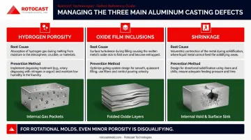
Oxide Film Inclusions
Aluminum forms dross rapidly when the melt surface is disturbed. Turbulent metal entry folds oxide films into the casting. The controls: keep the ladle close to minimize fall height, maintain a full basin throughout the pour, and design gating to deliver metal smoothly without direct impingement on cores or mold walls.
Shrinkage
Aluminum shrinks as it solidifies. Risers act as metal reservoirs to feed shrinkage as it occurs. Proper riser placement—sized and positioned to maintain directional solidification from the casting toward the riser—prevents internal voids. Validate final riser sizing against the casting's cross-sectional profile; it's geometry-specific.
What Distinguishes High-Quality Aluminum Casting
The properties that matter most in production:
- Uniform wall thickness for consistent heat transfer through the mold
- Dense casting structure free from internal porosity or shrinkage voids
- Smooth interior surface free from sand inclusions, tears, or cold shuts
Rotocast Technologies' foundry process is built around these requirements. Their castings use A356.2 grade aluminum, selected for its greater elongation, higher strength, and higher ductility compared to standard 356.0. The ".2" designation specifies strict chemical limits and primary aluminum feedstock, delivering tighter consistency than standard foundry grades.
With a workforce averaging 16 years' experience in specialty aluminum casting, Rotocast produces thin-walled castings in the ¼" to 3/8" range that meet the surface and density standards rotational molding requires.
From Sand Casting to Rotational Molds: What Quality Means in Practice
The foundry process doesn't end when the casting cools—it either enables or limits everything that happens in the molding plant afterward.
A sand-cast aluminum rotational mold must:
- Transfer heat quickly and evenly to the resin inside (requires uniform wall thickness)
- Produce consistent part wall thickness across every cycle (requires dimensional accuracy in the casting)
- Survive thousands of thermal cycles without cracking or distorting (requires dense, ductile casting structure)
- Deliver part surfaces that reflect the mold interior faithfully (requires a defect-free interior surface)
Each of these requirements traces directly back to casting quality. Porosity in the mold wall becomes a blowhole in the part. Uneven wall thickness creates hot spots that pull more resin toward thinner sections. A rough or pitted interior surface reproduces on every part the mold ever produces.
This is why foundry selection is a real purchasing decision for rotational molders, not a commodity choice. Rotocast Technologies built its foundry expertise on aluminum tire mold production, where the same dimensional accuracy and surface integrity requirements apply. That background translates directly into their rotational mold work, with veteran pattern makers and foundrymen collaborating across a vertically integrated operation that spans pattern making, foundry casting, CNC machining, finishing, and frame fabrication.
The results show in long-term customer relationships. Toter, Rubbermaid Commercial Products, and Swimways have relied on that consistency for years—supplier relationships at that scale only persist when the tooling performs cycle after cycle.
Frequently Asked Questions
What are the different tools used for making molds in the foundry?
The main categories are flask components (cope and drag), hand tools (riddles, rammers, trowels, slickers, vent wires, draw spikes), and structural accessories (gaggers, chaplets, chills). Hand tools shape and compact the sand; structural accessories support large sand masses and control how the casting solidifies.
How many times can you use a sand mold?
Sand molds are single-use—the mold breaks apart during shakeout to release the casting. The sand itself, however, can be reconditioned and reused across many pours by restoring moisture and clay content. Over time, fine particles degrade and must be replaced or directed to beneficial reuse applications like road subbase or soil amendments.
What is the difference between green sand and dry sand molds?
Green sand molds use moist, clay-bonded sand—the most common type, valued for fast production and easy collapsibility after pour. Dry sand molds are baked to remove moisture, gaining higher strength and dimensional stability at the cost of added prep time. That tradeoff makes dry sand the better choice for complex castings where moisture-related defects are a concern.
Why is aluminum commonly used in sand casting?
Aluminum pours at 1,250–1,400°F—roughly half the temperature of steel—which reduces refractory demands on the mold. It also has excellent fluidity for filling complex shapes, good machinability after casting, and a strong strength-to-weight ratio. Those combined properties make it one of the most widely cast non-ferrous metals.
What are the most common defects in aluminum sand castings and how are they prevented?
The three main defects are gas porosity, oxide film inclusions, and shrinkage voids. Gas porosity is prevented by degassing with nitrogen or argon; oxide films are minimized with low-turbulence gating; shrinkage voids are addressed through correct riser placement and directional solidification. All three respond well to consistent process discipline.
How does sand casting compare to die casting for aluminum?
Sand casting suits complex geometries, larger parts, lower volumes, and prototype work—tooling costs are low and mold design is flexible. Die casting is better for high-volume, smaller parts needing tighter tolerances, but tooling costs are much higher and geometry options are more constrained. For rotational mold tooling specifically, sand casting is the industry standard.