That relationship between pattern and casting is not approximate. It's direct. Surface imperfections in the pattern transfer to the mold; mold defects transfer to the casting. There's no stage where poor upstream work gets corrected downstream without cost.
This article covers what a foundry pattern is, how patterns are designed and built, the materials and types used, the dimensional allowances engineers must build in, and how the full casting journey unfolds from pattern to finished part.
Key Takeaways
- A foundry pattern is a replica of the desired casting used to form a mold cavity
- Patterns must be built larger than the intended part to compensate for metal shrinkage during solidification
- Pattern material (wood, metal, fiberglass, or printed polymer) is chosen based on production volume and required durability
- Five key allowances — including shrinkage, draft, and machining — must be engineered into every pattern
- The U.S. patternmaking workforce has declined 69% since 2007, making in-house pattern expertise a genuine competitive advantage
What Is a Foundry Pattern and Why Does It Matter?
The American Foundry Society defines a pattern as "the wood, metal, foam or plastic shape used to form the cavity in the sand." A pattern is not the final product — it's the tool that shapes the mold that produces the final product. Once the pattern is removed from the packed sand, the cavity it leaves behind becomes the vessel for molten metal.
Because metal shrinks as it solidifies, the pattern must be built larger than the intended casting. For aluminum, ASM International data puts that contraction at 1.3% (5/32 in./ft) — a small percentage that becomes significant at scale or when tight tolerances matter.
That shrinkage math also explains why everything surrounding the cavity — how metal enters, flows, and feeds the casting — has to be designed into the pattern from the start.
The Gating System: Channels, Risers, and Flow Control
Every mold requires a support infrastructure to control how metal enters and fills the cavity:
- Pouring cup — controls metal flow rate and captures slag before it enters the mold
- Sprue — the main vertical channel from the pouring cup down into the mold
- Runners — horizontal channels that distribute metal through the mold
- Gates — entry points where metal transitions from runner into the casting cavity
- Risers — reservoirs of liquid metal that feed the casting during solidification, preventing shrinkage voids
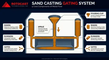
Each element must be sized and positioned correctly. An undersized riser starves the casting of feed metal. A poorly placed gate creates turbulence that traps gas. Both are built into or around the pattern before the first pour.
Pattern quality and casting quality are inseparable. A drip, crack, or rough patch on the pattern surface transfers through the mold directly to the casting. In rotational molding, this relationship is especially direct: the inner surface of every rotomolded plastic part mirrors the mold interior, so a single flaw in the casting reproduces across every part that mold ever produces.
The Role of the Pattern Maker
Patternmaking sits at the intersection of precision woodworking, applied metallurgy, and tooling engineering. Pattern makers must understand how to shape material accurately, how different metals behave as they cool, and how to compensate for that behavior before a single ounce of metal is poured.
Experienced pattern makers don't just execute designs. They interrogate them. They identify where shrinkage will concentrate, flag geometries that create difficult metal flow, and push back on designs that would cause defects downstream. That judgment comes from years of watching castings succeed and fail on the foundry floor.
A Workforce in Decline
That expertise is getting harder to find. According to Modern Casting, the number of metal and plastic patternmakers in the U.S. dropped 69% between 2007 and 2023. In 2023, only about 2,150 metal and plastic patternmakers were employed nationally, with roughly 38% of them working in foundries.
The consequences are practical:
- Pattern shop lead times have climbed to 12–14 weeks where 8–10 weeks was once standard
- Several pattern shops have closed outright in recent years
- Foundries without in-house pattern makers now compete for a shrinking pool of outside vendors
This is why foundries that retain in-house pattern makers hold a real advantage. Rotocast Technologies employs veteran pattern makers who work directly alongside the foundry casting team, which tightens the feedback loop between tooling design and production results.
Their workforce averages 16 years of experience in specialty casting and mold manufacturing — a depth that's increasingly rare in the industry.
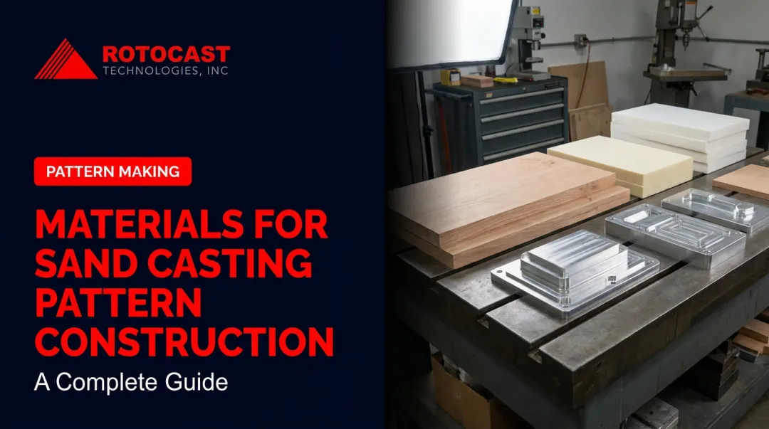
Pattern Materials: Wood, Metal, and Modern Options
Choosing a pattern material is a production economics decision. The right answer depends on expected casting volume, required dimensional accuracy, and how the pattern will be stored and reused.
Wood
Wood remains the most widely used pattern material. Sugar pine is favored for single or low-volume runs — it's soft, light, and easy to work by hand or machine. Honduras mahogany has historically been used for more demanding production runs, offering greater hardness and dimensional stability once properly cured.
The risk with wood is moisture. An uncured or poorly stored wood pattern can warp between production runs, compromising every casting made from it.
Metal
Aluminum is the most widely used metal pattern material, valued for its light weight and machinability. Cast iron is reserved for patterns that must withstand heavy, long-run production. Metal patterns are unaffected by humidity, hold dimensions precisely over thousands of cycles, and require minimal maintenance. The tradeoffs are real but manageable:
- Higher upfront cost than wood or resin
- Heavier to handle on the shop floor
- Harder to repair if the pattern is damaged
Fiberglass and Resin
Fiberglass and hard resin patterns occupy a useful middle ground — waterproof, dimensionally stable, and more durable than wood under production conditions. They're growing in use where moisture resistance matters but the investment in metal tooling isn't yet justified.
Additive Manufacturing
Some foundries now use 3D-printed polymer patterns for short runs and complex geometries. Faster production, excellent design freedom, and good dimensional accuracy from digital files make them practical for certain applications. Limitations include susceptibility to chemical binders used in some molding processes, surface finishing requirements, and difficulty of repair if the pattern is damaged.
Each material has a place depending on where a project sits in its production lifecycle. Rotocast Technologies works from wood master models as the primary pattern approach, accepting 2D data for conventional model making and 3D data formats for CNC-contoured pattern machining. Partnerships with local pattern shops extend that capability to CNC or foam pattern production when projects require it.
Types of Foundry Patterns Explained
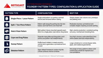
Pattern type selection is driven by part geometry and production volume. Here's how the main types differ:
| Pattern Type | Configuration | Best For |
|---|---|---|
| Single-piece (loose) | One-piece replica of the casting | Prototypes, low-volume runs |
| Split (two-piece) | Divided along a parting line | Parts without a flat back |
| Match plate | Both halves on one plate | Higher-volume, consistent production |
| Cope and drag plates | Two halves on separate plates | Large castings or very high volume |
| Sweep | Profile blade rotated around an axis | Large, rotationally symmetric parts |
| Skeleton | Open framework, not solid | Very large, simple shapes |
Single-piece patterns are the simplest option: a direct replica of the desired casting where the molder cuts gating into the sand by hand. Quick to make, but labor-intensive at the mold-making stage.
Split patterns divide along a parting line so each half presses into opposite sides of the mold (cope and drag) and withdraws cleanly. Use these when the casting geometry has no flat back.
Match plate patterns mount both halves on opposite sides of one plate, letting cope and drag impressions be made simultaneously. That combination of speed and consistency makes match plate the standard choice for higher-volume production runs.
Cope and drag plates take those two halves onto independent plates, enabling parallel mold-making on different machines — practical for large castings or wherever throughput is the priority. Choosing the right configuration at this stage directly shapes how the pattern performs through every step that follows.
Pattern Allowances: Building in the Right Dimensions
A pattern built to the exact dimensions of the desired casting will produce parts that are too small. Every pattern must incorporate several allowances before a single chip of wood is cut or a line is drawn.
Shrinkage Allowance
All metals contract as they solidify. Patterns must be made correspondingly larger. Typical values per ASM International:
- Gray cast iron: 0.83–1.3% (1/10 to 5/32 in./ft)
- Steel: 1.6–2.1% (3/16 to 1/4 in./ft)
- Aluminum: 1.3% (5/32 in./ft)
Pattern makers use a contraction rule — a ruler scaled to the appropriate alloy's shrinkage factor — so every measurement automatically builds in the correct allowance.
Rotocast's wood master models are expanded to account for both aluminum casting shrinkage and the subsequent plastic part shrinkage, since the final goal is a plastic part at the correct dimension, not just an aluminum mold.
Draft Allowance
Draft is the slight taper applied to the vertical walls of a pattern so it can be pulled from the mold without tearing the sand. Without it, sharp edges catch and crumble the mold cavity on extraction.
Typical draft angles run 1.5 to 3.0 degrees for manual molding, with tighter angles possible on machine-molded work. The exact value depends on pattern depth and surface finish requirements.
Machining Allowance
Surfaces that will be machined after casting need extra stock material, with the amount varying by alloy, part size, and tolerance requirements. Knowing where machining will occur also helps pattern makers position risers intelligently — that same extra stock often doubles as a clamping surface during post-cast operations.
Distortion Allowance
Some castings distort in predictable ways during cooling, driven by uneven thermal contraction across the part geometry. The pattern is intentionally built with a compensating pre-distortion — a camber — so the finished casting ends up at correct geometry. Predicting how a given geometry will move requires hands-on foundry knowledge; tables and formulas provide a starting point, but the final camber typically comes from reading how similar parts have behaved in the past.
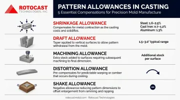
Shake Allowance
In practice, adequate draft usually eliminates the need to account for shake separately. The rapping required to loosen a pattern does slightly enlarge the mold cavity — making shake allowance technically a negative allowance — but well-drafted patterns absorb this without a dedicated dimensional adjustment.
From Pattern to Finished Casting: The Full Journey
Once a pattern is complete, the casting sequence follows a defined path:
- Mold making — the pattern is pressed into prepared foundry sand to form the mold cavity
- Pattern extraction — the pattern is carefully withdrawn, leaving the cavity intact
- Core setting — cores are placed to create internal voids where needed
- Mold assembly — cope and drag halves are clamped together
- Pouring — molten metal is poured through the sprue
- Solidification — risers feed liquid metal into the cavity to compensate for shrinkage
- Shakeout — the sand mold is broken away and the raw casting is retrieved
- Cleaning and finishing — gates, sprues, and risers are removed; the casting is cleaned, machined, and finished

Pattern Condition and Storage
The pattern's condition at every production run determines the dimensional consistency of all castings made from it. A warped or damaged pattern produces out-of-tolerance parts until the problem is caught — which may not happen until several castings have been rejected.
Wood patterns require dry, well-ventilated storage away from temperature swings. Beyond physical care, pattern custody is a genuine business continuity risk: when foundries close, manufacturers often struggle to locate their existing patterns — which is why dedicated pattern storage and refurbishment operations now serve manufacturers without in-house storage.
Digital CAD files reduce this risk meaningfully. A pattern designed in 3D software can be reproduced from the file if the physical pattern is damaged or lost.
Rotocast Technologies: Where This Process Lives
At Rotocast Technologies, the full casting journey described above plays out daily for rotational mold production. Their foundrymen have spent decades perfecting the pour of thin-walled aluminum castings using A356.2 grade aluminum.
That alloy is specified for a reason: greater elongation, higher strength, and higher ductility compared to standard 356.0 — achieved through stricter chemical limits and primary aluminum sourcing.
The complexity in rotomold castings is real: wall thicknesses of ¼" to 3/8", uniform throughout, over complex geometry, with interior surfaces that must be essentially defect-free because the plastic part surface will mirror every flaw in the mold. General sand casting tolerates surface variation that rotomold tooling simply cannot. Across North America, only a small number of foundries have built the process control to meet that standard consistently.
Rotocast's casting process draws directly from their heritage producing aluminum tire molds — work that demanded the same combination of thin walls, high surface quality, and consistent metal fill.
After casting, parts go through CNC machining, hand polishing, and optional texturing (shot peen, sandblast, acid etch, or mirror polish) before being inspected, framed, and shipped.
Frequently Asked Questions
What is a foundry pattern?
A foundry pattern is a replica of the object to be cast, used to form a cavity in a sand or plaster mold. Once the pattern is removed, molten metal is poured into that cavity to produce the finished casting.
What does a pattern maker do in a foundry?
A pattern maker designs and builds the physical patterns used to create casting molds, applying allowances for metal shrinkage, draft, and machining. The role draws on woodworking skill, metallurgical knowledge, and machining precision in equal measure.
What is the process of foundry pattern making?
The process moves through four main stages: designing the pattern with shrinkage and draft allowances, building it from the appropriate material, pressing it into foundry sand to form the mold cavity, then pouring molten metal once the pattern is withdrawn. Each stage directly affects the dimensional accuracy of the finished casting.
What are the different types of patterns in foundry?
The main types are single-piece (loose), split, match plate, cope-and-drag plate, sweep, and skeleton patterns — with simpler loose patterns used for low-volume work and match plate or cope-and-drag plates favored for high-volume production runs.
What are the three most common pattern materials for sand casting?
Wood (pine or mahogany for low-to-mid volume), metal (aluminum or cast iron for high-volume runs), and fiberglass or resin plastics (a durable, moisture-resistant mid-range option).
What is a wooden pattern?
A wooden pattern is a hand-crafted or machined replica of a casting made from timber (typically sugar pine or mahogany), used to form the mold cavity in sand casting. Wood is easy to shape and cut, making it a cost-effective choice for prototype work or short production runs.