Whether you're evaluating a supplier's part for the first time or deciding between forging and casting for a new component, understanding what a parting line actually tells you about the manufacturing process behind it will change how you design, inspect, and specify parts.
This article breaks down exactly how parting lines form in each process, what they look like, and what they mean for post-processing, structural integrity, and process selection.
Key Takeaways
- Forging parting lines mark where two die halves meet; excess metal (flash) squeezes out and is trimmed in a separate operation
- Casting parting lines form where mold sections join; sand casting shows a visible seam, investment casting has none, and die casting most closely resembles forging
- Forged flash is wider and thicker; cast seams are thinner fins typically removed by grinding
- Parting line location affects draft angle, dimensional tolerance, grain flow integrity, and finishing cost
- Knowing the difference helps engineers identify parts, anticipate post-processing, and make smarter process decisions
Forging vs. Casting Parting Lines at a Glance
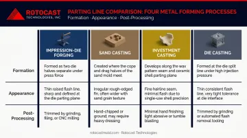
The table below compares how parting lines form, appear, and affect design decisions across the four most common forging and casting processes.
| Aspect | Impression-Die Forging | Sand Casting | Investment Casting | Die Casting |
|---|---|---|---|---|
| Formation | Metal forced into die gap under closing pressure; flash forms at die interface | Cope and drag mold halves join around a pattern; metal seeps into joint | No mold halves — ceramic shell surrounds wax pattern | Injected metal pressure separates die halves; flash forms at split |
| Appearance | Wide, raised flash line at largest cross-section; shear-trimmed witness mark remains | Thin cope-drag seam; ground or uneven surface texture | No parting line seam; gate and sprue removal marks only | Fine flash line at die split, plus gate/overflow trim marks |
| Post-Processing | Dedicated trim die shears flash; parting zone may need additional machining | Grinding and cleaning; machining for critical surfaces | Cut sprue, grind gates | Trim die removes flash, gates, and overflows |
| Design Implication | Parting line location dictates draft direction and marks the boundary of optimized grain flow | Affects dimensional accuracy across the seam; avoid critical tolerances across mold split | Preferred when all exterior surfaces must be seam-free | Keep critical dimensions within one die half; add projected-area tolerance |
What Is a Parting Line and Why Does It Exist?
A parting line is the boundary where two halves of a tool — whether a die or a mold — meet. Any process that uses a two-piece tool will produce one.
The physics is the same in both forging and casting: material under pressure finds any available gap. According to the Forging Industry Association's Product Design Guide, in impression-die forging, excess metal flows outside the die impression to form flash, which also helps build cavity pressure and ensures complete die fill. In die casting, NADCA explains that injected metal pressure tries to force die halves apart, producing flash at the parting plane in an analogous way.
What separates the processes is intent. In forging, flash relief is designed into the die — the flash gutter is a deliberate feature. In casting, the parting line is a consequence of mold assembly that must be managed rather than exploited.
Parting line location is a deliberate engineering decision. NADCA recommends settling it early alongside the part designer because it cascades into several downstream variables:
- Gate and vent placement
- Achievable tolerances on critical surfaces
- Cosmetic surface assignment
- Die life and maintenance access
The ASM Handbook Volume 14A treats parting line and grain flow as a core forging design topic for the same reason. Lock in the parting line before tooling is released, not after.
Parting Lines in Forging: How They Form and What to Expect
Flash Formation and Die Design
In impression-die forging, a heated billet is pressed between two matched die halves. As closing pressure builds, metal fills the die cavity and the excess flows outward through a flash gutter designed into the die perimeter. This is an engineered pressure management feature, not a defect. The flash thins and cools at the die edges, helping maintain internal cavity pressure that forces metal into fine detail.
According to the FIA Product Design Guide, flash gutters are deliberately formed in the die to receive excess metal and help the dies reach their intended closed position.
Appearance and Trimming
A forging parting line runs around the entire periphery of the part at the die split. The flash itself is a raised, rough-edged collar: wider and more prominent than anything you'd see on a sand casting seam. After trimming, a slight witness mark or land remains.
Trimming is a dedicated secondary operation:
- The forging is placed into a trim die matched to the part geometry
- Flash is sheared cleanly at the parting plane
- Trimming can be done hot or at room temperature
- The trim die is a separate cost item driven by forging size and complexity
Draft, Grain Flow, and Structural Significance
The parting line in a forging sits at the largest cross-section of the part, where draft requirements converge. The FIA reports typical finished-forging draft of 3 to 7 degrees, with precision aluminum forgings as low as 0 to 1 degree. Draft angles taper cavity walls from the die bottom toward the parting line, so the part can be released.
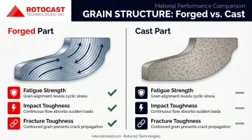
The parting line also marks the boundary of the optimized grain flow zone. Forging develops continuous grain structure that follows the part contour — a structural advantage castings cannot replicate through grain flow alone. That continuous structure improves:
- Fatigue strength
- Impact toughness
- Fracture toughness
Proper parting line placement also helps minimize end-grain exposure at part surfaces.
In safety-critical applications, match tolerance (displacement of one die half relative to the other at the parting line) is a documented inspection criterion. The FIA defines this based on trimmed forging weight and it is verified alongside ultrasonic and magnetic particle testing.
Parting Lines in Casting: How They Vary by Process Type
Casting doesn't produce one type of parting line — it produces several, and they look nothing alike depending on the process.
Sand Casting
In sand casting, a cope (top half) and drag (bottom half) are packed around a pattern, separated to remove it, then reassembled before pouring. The joint between cope and drag becomes the parting line. When liquid metal is poured, it can seep into that joint and solidify as a thin fin.
Per the American Foundry Society's terminology, the cope-drag interface is the source of the seam. A Casting Source article notes that greater tolerances are required for dimensions measured across the parting line because mold closing introduces variation.
Post-processing typically involves grinding, and the surface texture near the seam is noticeably rougher than a shear-trimmed forging surface — a useful visual differentiator.
Investment Casting
Investment casting is the exception to everything above. Because the mold is a single-piece ceramic shell formed around a disposable wax pattern, there are no mold halves and therefore no parting line. The only witness marks are where gates and sprues are cut off and ground after shell removal — per the Investment Casting Institute's process description.
This makes investment casting the preferred choice when all exterior surfaces must be seam-free.
Die Casting and Permanent Mold
Die casting uses hardened steel dies that open and close for each shot, making it functionally similar to forging in parting line behavior. Flash forms at the die split; gates, overflows, and vents are also located at the parting plane and removed in a trim die. NADCA's 2009 tolerance standards quantify this: for a 75 sq. in. projected area in aluminum, parting line tolerance adds +0.012 in. to linear tolerance, yielding a total standard tolerance of +0.026/-0.014 in.
Permanent mold casting behaves similarly, with supplier benchmarks suggesting across-parting-line tolerance of roughly ±0.025 in. for the first inch.
Aluminum Cast Molds for Rotational Molding
Die casting and permanent mold are single-use-per-cycle processes, but aluminum casting molds for rotational molding operate under continuous production pressure — which makes parting line placement a design decision, not just a manufacturing outcome. The parting line of the mold transfers directly to every finished plastic part it produces. A poorly positioned or poorly finished mold parting line shows up as a seam on every part run from that tool.
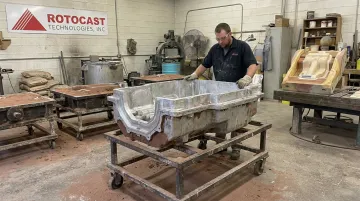
Rotocast Technologies, a sand casting rotational mold manufacturer in Akron, Ohio, controls this at the pattern stage. Veteran pattern makers work alongside the foundry team to determine where the parting line falls before any metal is poured, with each design validated by an engineer. Their process addresses several variables simultaneously:
- Wall thickness held to ¼–⅜ inch uniformly across the parting line zone for consistent heat transfer
- Parting line layout optimized for shutoff geometry and part release
- Pattern production and foundry work handled in-house to maintain alignment between design intent and cast result
Key Differences That Affect Design, Inspection, and Process Selection
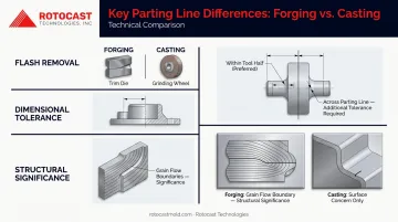
The Three Differences That Matter Most
1. Flash thickness and removal method Forging flash is thick and shear-trimmed with a dedicated die. Cast seams are thinner fins ground or sawed off. Die casting comes closest to forging — it also uses a trim die — but flash is typically finer. Sand casting requires manual grinding. Investment casting requires neither.
2. Dimensional implications In both forging and casting, dimensions measured across the parting line carry additional tolerance compared to dimensions within a single tool half. NADCA's projected-area tolerance model quantifies this for die casting. For forging, match tolerance between die halves is the equivalent concern. The rule is the same in both processes: keep critical dimensions within one tool half.
3. Structural significance In forging, the parting line zone is the boundary of optimized grain flow. Disrupting it through deep machining can affect directional properties — this matters for fatigue-loaded parts. In casting, the parting line is primarily a surface and dimensional quality concern, not a metallurgical one.
When to Choose Each Process
| Condition | Recommended Process |
|---|---|
| High fatigue or impact loads | Forging |
| Seam-free exterior surfaces required | Investment casting |
| Complex geometry, internal passages | Investment or sand casting |
| High-volume production, minor flash acceptable | Die casting |
| Large, low-volume industrial parts | Sand casting |
| Rotational mold tooling with surface-quality requirements | Cast aluminum with engineered parting line placement |
A pump housing illustrates this well: the cast housing accommodates complex fluid channels that would make forging impractical, with the parting line placed on a non-sealing flange face. The internal shaft is forged, where continuous grain flow and a parting-line-free stress zone are non-negotiable.
For rotational mold manufacturers, parting line placement in the aluminum casting mold directly determines where flash appears on every plastic part it produces — making it a tooling decision with downstream consequences throughout the production run. Rotocast's design review process covers product geometry, shutoff locations, and moldability together, locking in that placement before casting begins.
Conclusion
Both forging and casting produce parting lines, but they differ enough in cause, appearance, post-processing burden, and structural significance that treating them as the same feature leads to real mistakes.
Forging parting lines are a pressure management tool that defines the boundary of grain flow and requires dedicated trimming. Casting parting lines range from the obvious cope-drag seam in sand casting to effectively nothing in investment casting. Die casting sits in between, with fine flash and a trim die process that mirrors forging more than most engineers expect.
The right process depends on what your part actually needs:
- Fatigue resistance and grain integrity — forging
- Geometric complexity and seam-free surfaces — investment casting
- High-volume production with manageable flash — die casting
For rotational mold tooling, parting line quality in the aluminum mold directly determines surface quality in every plastic part it produces. That makes the decision worth getting right early. Rotocast Technologies works with rotational molders and product engineers during design review — before a pattern is made — to make sure parting line placement supports both tooling performance and final part quality.
Frequently Asked Questions
When should you use casting versus forging?
Forging is preferred when strength, fatigue resistance, and grain integrity are non-negotiable : loaded shafts, brackets, and safety-critical components. Casting suits complex geometries, internal passages, or alloys that cannot be effectively worked in solid state. Part volume and acceptable finishing cost also factor in.
Are forged parts stronger than cast parts?
For the same material, forged parts generally exhibit higher fatigue strength and impact resistance due to refined, continuous grain flow — castings lack that directional strength. That said, investment cast parts in specific superalloys can approach forging performance when geometry makes forging impractical.
How can you tell if a part is cast or forged?
Forgings show a wider, shear-trimmed flash line at the largest cross-section with tapered draft on side walls. Sand castings show a thinner, ground seam with a rougher surface texture. Investment castings have no parting line seam but show gate and sprue removal marks. Die castings resemble forgings but with finer flash.
What causes parting lines in forging and casting?
In forging, the parting line forms because metal is squeezed between two die halves under pressure and excess flows into the gap as flash. In casting, it forms where mold sections join and liquid metal seeps into the joint before solidifying. The mechanism is pressure-driven in both cases, but solid versus liquid material state produces distinctly different results.
Does investment casting have parting lines?
No. Investment casting uses a single-piece ceramic shell formed around a wax pattern, so there are no mold halves to create a seam. It's the preferred method when all exterior surfaces must be free of parting line marks. Witness marks from gate and sprue removal are the only post-processing indicators.
How do parting lines affect part quality?
A poorly placed parting line can intersect sealing surfaces, load-bearing zones, or cosmetically critical faces — increasing finishing cost and the risk of dimensional non-conformance. Both forging and casting require deliberate parting line placement during the design phase, before tooling is committed, to minimize those risks.