Introduction
Committing to a cast aluminum rotomold before a design is fully validated is a real gamble. Traditional tooling requires pattern production, foundry casting, CNC machining, and finishing — a sequence that can stretch across weeks or months before a single plastic part rolls off the machine. If the geometry needs adjustment, you're looking at rework costs and schedule delays that compound quickly.
Additive manufacturing changes the equation for that front-end risk. Not by replacing cast aluminum as the production mold material — it can't — but by shortening the path to a validated design and a finished metal tool.
This guide covers:
- What AM actually means for rotomold tooling
- Which techniques apply and where they fit in the process
- The real benefits and honest limitations
- A practical framework for deciding when AM makes sense versus going straight to cast aluminum
Key Takeaways
- AM in rotomold tooling means faster patterns and sand molds — not a replacement for cast aluminum production tools
- Binder-jetted sand molds can compress foundry lead times by several weeks compared to conventional pattern methods
- Most polymer AM materials fail well below rotomold oven temperatures (400–850°F), making cast aluminum the preferred production mold material
- The strongest use cases for AM: design validation, complex pattern geometries, consolidated single-piece patterns, and low-volume prototypes
- The hybrid approach — AM for iteration, cast aluminum for production — cuts tooling timelines without sacrificing mold longevity
What Is Additive Manufacturing for Rotomold Tools?
ISO/ASTM 52900 defines additive manufacturing as joining material from 3D model data, typically layer by layer, as opposed to subtractive or formative methods. Of the seven recognized process categories, three are most relevant to rotomold tooling: material extrusion (FDM/FFF), binder jetting, and vat photopolymerization — each with distinct trade-offs in surface quality, thermal resistance, and cost.
For rotomold tooling, the key distinction is where AM actually fits. It does not mean 3D-printing a mold and running production rotomolding cycles through it. It means using AM to produce patterns, masters, sand molds, and prototype fixtures that feed into the conventional metal mold workflow — or cut significant time out of it.
Two Primary Applications
Pattern production for foundry casting The printed part serves as a physical pattern in a sand casting process. The final production tool is still cast aluminum — AM changes how the pattern is made, not what the mold is made from.
Prototype and short-run tooling 3D-printed tools can handle early design validation cycles before committing to full production investment, though thermal limitations covered later in this guide apply.
Why Rotomold Tooling Is Different
Rotomold tools operate under low pressure, which differs sharply from injection molds. They face prolonged oven heat exposure every cycle, which creates strict requirements any AM approach must respect:
- Uniform wall thickness for consistent heat transfer to the resin
- Surface quality that translates directly to part exterior finish
- Thermal durability across hundreds or thousands of cycles
These constraints explain why cast aluminum remains the production standard. The sections that follow break down exactly where AM fits in that workflow — and where it falls short.
AM Techniques Used in Rotomold Tooling
FDM/FFF: Accessible Pattern Making
Fused Deposition Modeling is the most accessible AM approach for rotomold pattern work. FDM printers in ABS or ASA can produce physical patterns quickly for checking draft angles, geometry, and fit before any foundry work begins.
Surface quality is the tradeoff. Research from Toronto Metropolitan University found ABS FDM patterns produce Ra roughness values around 15 µm — rough enough that sanding, sealing, or coating is required before a pattern is usable for casting. Stratasys industrial FDM accuracy is documented at ±0.0035 in or ±0.0015 in/in, which suits geometry checking but demands careful finishing for casting applications.
SLA: Better Surface, Smaller Scale
Stereolithography and vat photopolymerization processes produce significantly smoother results than FDM. Published SLA investment casting pattern research reports minimum Ra values of 0.882 µm and dimensional deviations from -0.21 to 0.12 mm — a substantial improvement over FDM for detail patterns.
Brittleness is the limiting factor. Formlabs Clear Resin V5 lists elongation at break of just 8–10%, so thin features on complex patterns need careful handling. SLA is best suited for smaller, high-detail patterns where surface finish matters more than impact resistance.
SLS: Geometry Freedom Without Supports
Selective Laser Sintering produces strong, near-isotropic parts without support structures, which benefits complex pattern geometries with undercuts, internal features, or organic curves that would require multi-piece construction with machined patterns. Unsintered powder supports the part during building, making complex geometry straightforward to produce in a single build.
EOS PA12 SLS material lists tensile strength at 48 MPa and strain at break of 18%, which handles pattern use well. The thermal ceiling (deflection temperature at 64°C under load) still disqualifies it as a direct production rotomold tool.
Binder-Jetted Sand: The Fastest Route to Cast Aluminum
For teams whose end goal is a cast aluminum mold, binder jetting on sand is the strongest AM option. Rather than printing a pattern, the process prints the sand mold or core directly from CAD data, eliminating the hard pattern step entirely.
voxeljet reports that sand molds and cores can be produced in a few hours, with time savings of several weeks versus conventional methods. ExOne documents complex core designs replacing assemblies of over 20 pieces with a single-piece core, reducing foundry prep time and eliminating assembly error risk.
Large-Format AM: For Tool-Scale Patterns
Rotomold tools are often large. Standard FDM build volumes (the Stratasys F900 reaches 914 × 610 × 914 mm) can handle many patterns but not all. Large-format AM systems using polymer extrusion can produce tool-sized masters or segmented pattern assemblies for oversized geometries, though surface finishing and thermal validation remain required before production use.
Comparing AM Techniques at a Glance
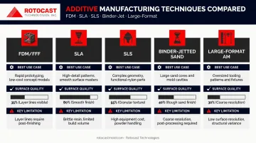
| Technique | Best Use Case | Surface Quality | Key Limitation |
|---|---|---|---|
| FDM/FFF | Draft angle and fit checks | Ra ~15 µm (requires finishing) | Rough surface; needs sanding/sealing |
| SLA | Small, high-detail patterns | Ra <1 µm | Brittle; poor impact resistance |
| SLS | Complex geometries, undercuts | Moderate | Low thermal ceiling; not production-grade |
| Binder-Jetted Sand | Direct cast aluminum molds | N/A (no pattern needed) | Requires foundry partnership |
| Large-Format AM | Oversized tool-scale masters | Varies | Surface finishing and thermal validation required |
How AM Fits Into the Rotomold Tooling Workflow
Rotocast Technologies' standard production workflow illustrates where AM creates the most leverage. The full sequence runs:
- Design review and engineering validation — CAD files reviewed for moldability, wall thickness, parting line layout, and shutoff
- Pattern production — Wood master or CNC-machined pattern, expanded for aluminum and plastic shrink
- Foundry casting — A356.2 aluminum poured into sand mold cavity
- CNC machining — Secondary machining where tight tolerances are required
- Finishing and texturing — Hand polishing, shot peen, sandblast, acid etch, or mirror polish
- Framing and assembly — Frame designed for the specific molding machine and environment
- Final inspection and shipment
AM enters at step 2, replacing or supplementing the wood or CNC-machined pattern. When binder-jetted sand is used, it can replace both the hard pattern and the conventional sand preparation step, accelerating the path to step 3.
Secondary AM Applications in the Workflow
AM isn't limited to the pattern stage. Other practical uses include:
- Prints fill ports, vent details, and parting line inserts as standalone components
- Produces locating fixtures and jigs for assembly and quality inspection
- Creates short-run validation pieces checked against CAD geometry before committing to a production mold
Rotocast's in-house machine shop produces fill ports, threaded insert pins, pull pins, and inner gas manifolds through conventional machining. AM becomes the faster option when a component needs to be revised mid-development — skipping the setup time that conventional machining requires for a single revised part.
Key Benefits of Using AM for Rotomold Tool Development
Lead Time Compression
Binder-jet sand printing compresses casting input preparation from several weeks to hours. ExOne reports projects that traditionally took months completed in weeks or days, with one case producing a week's worth of production cores in 18 hours.
For FDM or SLS patterns, the advantage is similar: a geometry check that previously required a machined wooden pattern taking days to fabricate can now be produced overnight.
Geometric Freedom
Complex rotomold geometries — deep draws, organic curves, compound undercuts — create real challenges for machined patterns. Multiple components, special fixtures, and multi-piece assemblies add time and introduce alignment risk.
A single printed pattern can incorporate features that would otherwise require an assembly of separate machined pieces. The ExOne-documented case of replacing a 20-piece core assembly with one binder-jetted part is an extreme example — but the principle applies to everyday rotomold complexity as well.
Design Validation Before Metal Commitment
Physical validation before a mold is cast has genuine value, especially for large parts where errors are expensive. AM-produced patterns allow rotational molders and their customers to verify:
- Wall distribution assumptions across complex geometry
- Draft angles and demold clearance
- Insert positioning and fit
- Part geometry against assembly requirements
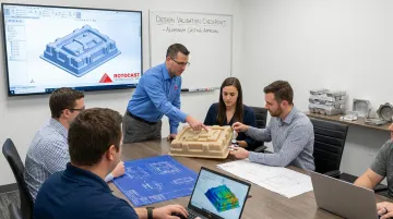
At Rotocast Technologies, customers review the model or part design after the pattern is produced and before it is cast in aluminum — a built-in checkpoint that catches errors before the production investment is made.
Speed of Iteration
When a design change is needed, AM allows a revised pattern in days. Reworking a machined wooden pattern or a cast mold takes far longer and costs more. That speed keeps development cycles moving without locking in decisions prematurely.
Limitations and Design Considerations
Thermal Performance: The Hard Constraint
LyondellBasell's rotomolding process guide states normal oven temperatures run 400 to 850°F (205 to 455°C). Against that range, common AM polymer materials fall well short:
| Material | Heat Deflection Temperature | Implication |
|---|---|---|
| ABS-M30 (FDM) | 103.8°C / 219°F at 66 psi | Below production oven temp |
| Tough PLA (FDM) | 58.3°C / 137°F at 0.455 MPa | Not suitable |
| EOS PA12 (SLS) | 64°C / 147°F at 1.80 MPa | Pattern use only |
None of these survive production rotomolding cycles. AM's role is confined to pattern-making — the printed part is consumed in the casting process, never exposed to oven heat.
Surface Finish Post-Processing
Layer-based AM processes produce surfaces that require work before casting use. FDM ABS patterns at 15 µm Ra need sanding, priming, or coating to produce a clean casting impression. Skipping this step transfers surface texture into the cast mold interior — which then transfers to every rotomolded part produced from that tool.
That surface prep work happens before the sand is rammed — downstream finishing can only work with what the pattern provides. Rotocast's post-cast finishing options include:
- Hand polish and mirror polish
- Shot peen and sandblast texturing
- Acid etch
- Teflon coating
Each of these refines the mold interior, but none can fully compensate for a poorly prepared pattern surface.
Build Volume Constraints
Many standard AM systems can't print large rotomold patterns in a single build:
- Stratasys F900 (FDM): 914 × 610 × 914 mm
- Formlabs Form 4L (SLA): 353 × 196 × 350 mm
- voxeljet VX4000 (sand): 4 × 2 × 1 m
Large tools require segmented patterns assembled before casting, which introduces seam lines and alignment tolerances that must be managed before the sand is rammed. Large-format FDM systems and binder-jet sand printing reduce the need for segmentation, but both carry significantly higher equipment and per-part costs — a trade-off worth evaluating against the complexity of the tool geometry.
When to Choose AM vs. Traditional Cast Aluminum Molds
Decision Framework
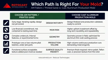
| Factor | Choose AM Pattern / Printed Sand | Choose Cast Aluminum Production Mold |
|---|---|---|
| Design maturity | Geometry still changing | Geometry frozen |
| Main risk | Schedule, iteration, pattern complexity | Heat transfer, cycle consistency, durability |
| Geometry | Complex cores, undercuts, multi-piece patterns | Proven geometry |
| Production volume | Prototype or low-volume validation | Committed production run |
| Surface quality priority | Prototype-grade acceptable | Production interior finish required |
Where Cast Aluminum Is the Only Correct Answer
For production rotomolding, cast aluminum wins on every metric that matters long-term:
- Thermal conductivity: A356.0-T6 sand-cast aluminum delivers 151 W/m·K — no polymer AM material approaches this
- Oven durability: Cast aluminum handles the 400–850°F oven environment cycle after cycle without degradation
- Surface quality: A properly finished cast aluminum mold interior produces consistent, defect-free part surfaces that reflect the mold directly
Rotocast Technologies uses A356.2 aluminum — a stricter-chemistry version with greater elongation, higher strength, and higher ductility than standard 356.0, produced from primary aluminum with tight chemical limits. Their proprietary thin-wall casting process consistently achieves ¼" to 3/8" uniform wall thickness, which is the specification that drives even heat transfer and consistent part wall distribution.
The Hybrid Workflow: AM Then Cast Aluminum
The right strategy for development programs isn't a choice between AM and cast aluminum — it's using each where it performs best:
- AM phase: Produce patterns quickly, validate geometry, iterate on design, compress development schedule
- Transition: Once design is frozen, move to a production cast aluminum mold using a validated CAD file
- Production: Run the aluminum tool for the life of the product
This sequence avoids the false trade-off between speed and quality. AM buys time and reduces iteration risk during design uncertainty. Cast aluminum delivers the thermal performance, surface consistency, and tool durability that production rotomolding requires.
The pattern-to-casting handoff is where many programs stumble. It requires a foundry that understands rotomold-specific tolerances and surface requirements, not general aluminum casting. Rotocast Technologies has focused exclusively on this since 1956, developing casting processes and in-house pattern capabilities built around the specific demands of rotomold tooling.
Frequently Asked Questions
Can 3D printed molds be used directly for rotational molding production?
For short-run or prototype validation, direct AM tooling is possible. For production, no — rotomold oven temperatures of 400–850°F exceed the heat deflection limits of every common AM polymer material, including ABS, PLA, and SLS nylon. Cast aluminum is the only production-viable mold material.
What types of rotomold tooling components are best suited for additive manufacturing?
AM is best suited for components that benefit from geometric freedom without sustained oven exposure:
- Sand casting patterns and core boxes
- Prototype validation tools and inserts
- Parting line details and vents
- Locating fixtures, jigs, and foaming fixtures
How does AM change the lead time for developing a rotomold tool?
AM can compress the pattern-making phase from several weeks to days or hours, depending on the technique. Binder-jetted sand eliminates the hard pattern step entirely, cutting the most time-consuming pre-casting step on the path to a first cast aluminum mold.
What is the best AM process for creating rotomold tool patterns?
It depends on part size and required detail. SLS handles complex geometries without support structures; SLA delivers the best surface finish for smaller, high-detail patterns. Binder-jetted sand is the strongest choice when the goal is cast aluminum tooling with the shortest lead time.
What are the biggest limitations of using additive manufacturing for rotomold tools?
The main constraints are:
- Thermal limits — all AM polymers fall well below production oven temperatures
- Surface finish requires post-processing before casting use
- Build volume restricts large tool patterns
- Long-term durability cannot match cast aluminum production molds