The problem is that spider defects compromise structural integrity, drive up scrap rates, and often signal something deeper: a mold geometry problem, a process parameter that's drifted, or a material issue that slipped through incoming inspection. According to Poly Processing's research on environmental stress cracking, 15–40% of premature plastic part failures in the field are attributable to surface-initiated microcracking — the same failure family spider defects belong to.
This article covers the root causes of spider defects, the consequences of leaving them unaddressed, and the specific prevention measures that eliminate them at the source.
Key Takeaways
- Spider defects are radiating crack or crazing patterns caused by stress concentrations at corners, thin-wall zones, or incompletely fused areas
- Primary causes: sharp mold corners, incorrect oven temperatures or cycle times, rapid or uneven cooling, and material issues
- Prevent them through mold design corrections, PIAT-based process control, two-stage cooling, and verified material specs
- Even hairline spider cracks propagate under service loads — reject affected parts rather than attempt repair
- Sustain long-term control with documented process standards, scheduled mold inspections, and trained operators
Common Causes of Spider Defects in Rotomolding
Spider defects originate at stress concentration points — corners, thin-wall transitions, or zones of incomplete powder fusion — and propagate outward under thermal or mechanical stress. They rarely have a single cause, and typically emerge when two or more contributing factors coincide.
Sharp Corners and Insufficient Radii
When a mold has sharp internal corners, plastic powder cannot flow and sinter evenly into those geometry features. This is called bridging — the powder arcs across the corner instead of filling it, leaving a locally thin, underfused wall section underneath.
That underfused zone becomes a stress initiation point. The part may look acceptable immediately after demold, but spider cracks develop during cooling, handling, or in service — almost always at corners and wall transitions.
The ARM Design Guide recommends an 0.250 in ideal inside corner radius for rotomolded polyethylene, and a minimum angle of 30° for PE powder flow. ARM also notes that rotomolded parts naturally thin on inside corners and thicken on outside corners — meaning inside corners already carry both a geometry stress concentration and a thinner wall. That combination is where spider cracks start.
LyondellBasell's rotomolding guide reinforces this: ribs narrower than 4× wall thickness and passages with insufficient radii cause bridging that produces voids and weak spots no amount of process adjustment can fully compensate for.
Incorrect Oven Temperature or Cycle Time
There are two opposite failure modes here, and both produce spider-like cracking:
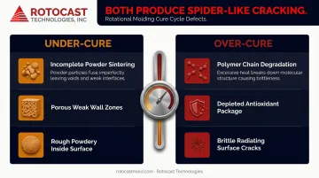
- Under-cure: Insufficient heat or time leaves powder incompletely sintered. The wall has porous, weak zones where cracks originate under stress. Parts may also show a rough, powdery inside surface and reduced impact strength.
- Over-cure: Excessive temperature or cycle time degrades polymer chains and depletes antioxidant packages. The material becomes brittle, and radiating surface cracks appear — often indistinguishable from under-cure cracking without examining the part wall cross-section.
Both failure modes are common when operators rely on fixed oven time rather than Peak Internal Air Temperature (PIAT) as the control parameter. PIAT directly indicates whether the resin has reached full sintering without crossing into degradation. Ferry Industries' RotoLog system identifies melt stages and records PIAT inside the mold specifically because external oven time cannot confirm what's happening at the part wall.
Oven thermocouple drift is another silent contributor: when calibration lapses, the actual mold temperature diverges from displayed values, pushing the process toward either failure mode without operators noticing the shift.
Rapid or Non-Uniform Cooling
Cooling too aggressively creates large thermal gradients between the outer mold wall and the still-hot inner plastic layer. The outer surface crystallizes and shrinks first; the inner surface follows later. That differential shrinkage generates internal tensile stresses that manifest on the part surface as spider cracks.
A 2018 study published in AIP Conference Proceedings confirmed that conventional outside cooling causes the outer PE surface to cool faster than the inner surface, creating crystallinity differences and internal stresses that increase warpage, excessive shrinkage, and scrap risk.
Common triggers include:
- Switching to faster production cycles without re-validating cooling parameters
- Applying cooling water before the part has passed through its critical shrinkage phase
- Uneven airflow in the cooling area, causing one side of the mold to cool significantly faster
Material Issues and Contamination
Material problems create localized weak spots that crack in spider patterns under normal service stress — and no process adjustment fixes a material problem at its source. Common culprits include:
- Wrong resin grade for the application
- Antioxidant package depleted by prior overheating
- Batches contaminated with moisture, regrind, or foreign particles
Degraded or contaminated material looks visually normal, which is why this cause is so often missed. Verifying resin grade, melt flow index, and material lot documentation before each production run is the only reliable screen.
What Happens If Spider Defects Are Ignored
A hairline spider crack pattern that looks cosmetic at demold is a stress failure waiting to propagate. Under service loads, UV exposure, or temperature cycling, the crack network grows. In structural parts like chemical storage tanks or industrial containers, that growth path leads to full wall failure, not a surface blemish that can be ignored.
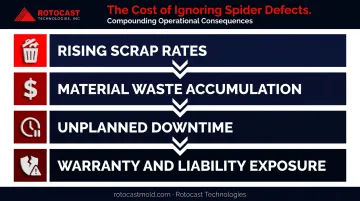
The operational consequences compound quickly:
- Scrap rates climb as defects recur across production runs
- Material waste accumulates with each rejected part
- Downtime follows when root cause investigation starts after a defect spike, not before it
- Warranty and liability exposure mounts when defective parts reach end users in fluid containment or load-bearing applications
Industry guidance on rotomolding consistently identifies under- and over-cured parts as long-term failure risks. Spider defects are one of the clearest visible indicators that structural reliability is already compromised before the part ever enters service.
Warning Signs You're About to Experience Spider Defects
Spider defects give early signals before they become full scrap events. Watch for:
- Consistent crazing in the same location across multiple runs — repeatability points to a mold design or process parameter issue, not chance
- Parts that pass visual inspection but develop cracks within 24–48 hours — residual stress relaxing after demold; strong indicator of rapid cooling or over-cure
- Stress whitening around corners at demold — internal stresses are already high enough to cause micro-damage during extraction; demolding difficulty often accompanies this
Any of these signals is reason to stop production and investigate before the next run — catching the pattern early is far less costly than a defect spike mid-campaign.
How to Prevent Spider Defects
Preventing spider defects requires addressing mold geometry, process control, cooling protocol, and material management together — no single fix covers all four failure modes.
Optimize Mold Design with Proper Radii and Uniform Wall Thickness
The actionable design rules for PE rotomolding:
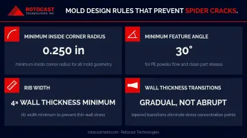
- Minimum inside corner radius: 0.250 in (ARM's recommended target for polyethylene)
- Minimum feature angle: 30° for PE powder flow — below this, bridging becomes likely
- Rib width: at least 4× wall thickness to prevent powder bridging in narrow passages
- Wall thickness transitions: gradual — abrupt changes create differential shrinkage stress during cooling
Adequate radii allow powder to flow and sinter fully into corners, eliminating the underfused zones that start spider cracks. Gradual wall transitions reduce the differential shrinkage stress that drives crack propagation during cooling.
Precision-cast aluminum molds with high-quality interior surfaces give designers the dimensional accuracy needed to hold these radius and thickness specifications throughout the mold's production life. Rotocast Technologies produces aluminum rotational molds with uniform wall thickness typically ranging from ¼" to 3/8", cast using A356.2 grade aluminum alloy, a specification with stricter chemical limits and greater ductility than standard 356.0. Their in-house foundry and tooling department validate wall thickness and parting line layout for each design.
Rotocast also offers collaborative design review services to identify geometry factors that could create molding problems before the mold is built — catching issues at the design stage costs far less than correcting them in production.
The mold interior surface is equally important: because the outside surface of a rotomolded part directly mirrors the mold cavity, any defect or stress concentration on the interior transfers to the part wall.
Good mold geometry sets the conditions for success — but process control determines whether those conditions are met in every cycle.
Validate and Control Oven Temperature and Cycle Time
- Establish cycle parameters using PIAT monitoring rather than fixed oven time alone
- Calibrate oven thermocouples on a scheduled basis within your quality system
- Log cycle data — PIAT, cycle duration, oven temperature — for every production run
- Revisit validated parameters immediately when introducing a new resin grade, changing mold wall thickness, or after any oven maintenance or thermocouple replacement
PIAT-based control catches both failure modes: it confirms the resin reached full sintering (preventing under-cure) and alerts operators before temperatures cross into polymer degradation (preventing over-cure). The SPE Rotational Molding Division has identified 370–430°F PIAT as the correct cure window for PE, though the specific setpoint is grade- and part-specific — validated recipes for each mold/resin combination are more reliable than a universal number.
Implement Controlled, Two-Stage Cooling
The protocol that prevents differential shrinkage stress:
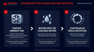
- Stage 1 — Forced ambient air: Bring the mold surface temperature down gradually through the critical crystallization and shrinkage phase before introducing any water
- Stage 2 — Water mist or cooling water: Introduce only after the part has passed through the critical shrinkage phase, when the risk of generating tensile stress from thermal gradients is meaningfully lower
- Maintain mold rotation throughout the entire cooling phase to prevent pooling and uneven wall thickness
LyondellBasell specifically recommends this air-first, then water approach for cases where non-uniform cooling is causing warpage and shrinkage problems. The AIP 2018 study showed that controlled internal cooling could reduce cycle time by 12–16% without the stress and dimensional penalties of unvalidated quenching — faster cooling is achievable, but only when the cooling curve is validated.
Highest-risk scenarios for rapid cooling damage: switching to a faster production cycle, molding thick-walled parts, and running in ambient temperatures significantly below normal.
Verify Material Specifications and Establish Handling Standards
Before each production run:
- Confirm resin grade and melt flow index match the mold design specification
- Inspect material for moisture, foreign contamination, agglomeration, or discoloration
- Track material lot numbers and flag any lot that produces consistent defects for supplier investigation
Contaminated or degraded material introduces weak points that process optimization cannot overcome. Lot tracking also gives you the data to distinguish a process problem from a resin problem — a distinction that matters when you're troubleshooting a recurring defect.
Tips for Long-Term Prevention and Control
Sustaining spider defect prevention beyond the immediate fix requires these practices:
- Inspect molds on a scheduled basis — check corner integrity, surface finish, and parting line condition. Surface damage and parting line wear create new stress concentration points over time. For molds already in production service, Rotocast Technologies provides mold repair and refurbishment, including re-machining and rebuilding to restore structural integrity.
- Log every production run — record cycle parameters, cooling protocol, and material lot, then correlate that data with any defect observations to catch process drift before it produces a defect spike.
- Train operators to recognize early warning signs: stress whitening, micro-crazing, and demold resistance are all actionable indicators. Empower them to flag these observations without waiting for a formal QC rejection.
- Deploy real-time monitoring tools — IAT probes or infrared thermometry systems provide objective oven and cooling performance data rather than relying solely on operator observation.
Conclusion
Spider defects in rotomolding are not random. They have identifiable causes — sharp mold corners, process parameter drift, aggressive cooling, and material problems — and each cause has a specific, actionable fix.
- Consistent defects in the same location point to a specific root cause; that repeatability is diagnostic, not bad luck
- Prevention costs far less than reaction: addressing mold design, process parameters, cooling protocols, and material verification up front avoids the compounding costs of scrap, rework, unplanned downtime, and warranty exposure
- Early warning signs are real signals: stress whitening, micro-crazing at demold, and 24–48 hour crack development are the process telling you something before it becomes a production crisis
Mold design and manufacturing quality underpin all of this. Generous corner radii, uniform wall thickness, and smooth interior surfaces eliminate the stress concentration geometry before a single cycle runs. At Rotocast Technologies, that's where the work starts — precision CNC machining, high-surface-quality thin-wall castings, and 70 years of foundry expertise built specifically for the rotational molding industry. Getting the process parameters right matters. So does the mold those parameters are running through.
Frequently Asked Questions
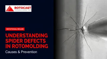
What are spider defects in rotomolding?
Spider defects are stress-crack or crazing patterns that radiate outward from a point on a rotomolded part's surface, resembling a spider web. They result from localized stress concentrations caused by mold geometry issues, process problems, or material deficiencies.
Does machine type affect spider defect risk?
Yes. Carousel machines allow independent arm timing, which makes it easier to dial in cure uniformity per part. Shuttle machines share a common oven, so one arm's settings affect others. Rock-and-roll machines, used for long slender parts, can create uneven heat zones — all of which raise spider defect risk if not managed carefully.
How does mold design contribute to spider defects?
Sharp corners, insufficient radii, and abrupt wall thickness transitions prevent plastic powder from fully sintering into those features. The result is a thin, underfused zone that becomes a crack initiation point under thermal or mechanical stress, with cracks propagating outward from that weak area.
Can spider defects be repaired after molding?
No reliable repair restores original structural integrity in a spider-cracked rotomolded part. Parts with spider defects should be rejected and the root cause addressed in the mold or process. Cosmetic repairs may mask the surface but leave the structural weakness intact.
What cooling mistake most commonly causes spider defects?
Applying cold water cooling before the part has passed through the critical shrinkage phase is the most common cooling-related cause. The thermal gradient between the rapidly cooling outer mold wall and the still-hot inner plastic generates tensile stresses that manifest as spider cracks on the part surface.
How do I distinguish spider defects from other rotomolding surface defects?
Spider defects show a radiating crack pattern from a central stress point — unlike pinholes (localized porosity), bubbles (trapped gas), or warpage (shape distortion), none of which share that pattern. When the same location is affected across multiple parts, that's your clearest sign of a specific mold geometry or process cause.