This guide covers what aluminum foundry compression tooling is, how it's produced, why aluminum outperforms steel in key tooling applications, and what separates a capable foundry partner from one that creates problems downstream. Whether you're evaluating a new mold for rotational molding, a urethane casting tool, or a composite compression die, the engineering fundamentals are the same.
Key Takeaways
- Aluminum compression tooling is cast near-net-shape, then CNC-machined to final tolerances, enabling complex geometries at lower cost than billet-machined steel
- A356 and 6061-T6 aluminum alloys conduct heat at 151–167 W/m·K, versus 25–42 W/m·K for common tool steels, giving aluminum a measurable cycle time advantage over steel tooling
- Uniform wall thickness is the most critical design variable — uneven walls cause thermal hot spots, part defects, and early tool fatigue
- Draft angles, parting line placement, and interior surface quality must be engineered at the pattern stage; corrections after casting are costly and often incomplete
- Integrated foundries handling pattern making, casting, and CNC machining under one roof reduce tolerance stack-up, lead time, and quality risk
What Is Aluminum Foundry Compression Tooling?
Compression tooling refers to molds or die sets that shape a material — rubber, thermoset composite, or plastic — by applying compressive force between two tool halves. This distinguishes it from injection molding (pressurized cavity fill through a gate) and rotational molding (gravity-driven, low-pressure rotation inside a heated oven).
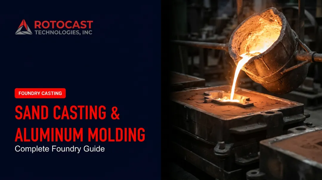
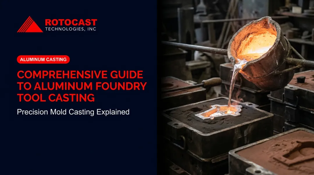
The "foundry" distinction matters: aluminum compression tooling is produced by pouring molten aluminum into a prepared pattern, yielding a near-net-shape casting that is then finish-machined to final dimensional requirements.
Milling the tool from solid billet, by contrast, becomes expensive and time-consuming when the geometry is large, curved, or complex. Casting lets the foundry establish most of the shape in metal; the CNC machine removes far less stock to reach tolerance.
Where aluminum foundry compression tooling appears:
- Rotational molds — thin-walled cast aluminum tools for hollow plastic products, from small industrial components to large containers
- SMC/BMC composite compression dies — tooling for automotive body panels and structural brackets using sheet or bulk molding compound
- Urethane and vacuum forming molds — specialty castings for lower-pressure forming applications
- Rubber vulcanization molds — compression dies for thermoset rubber parts
Rotocast Technologies, based in Akron, Ohio, specializes in the rotational molding and specialty casting segments of this market, producing cast aluminum molds in A356.2 alloy — along with urethane and vacuum forming tooling — since 1956.
The Foundry Casting Process for Compression Tooling
Pattern and Mold Making
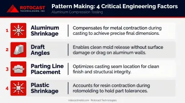
Pattern making is the most consequential step in the entire process. The master pattern defines every geometry the finished tool will carry, and mistakes made here travel downstream into every casting produced from it.
Experienced pattern makers must account for:
- Aluminum shrinkage — the casting contracts as it solidifies; the pattern must be dimensionally expanded to compensate
- Draft angles — surfaces that release the pattern from the mold must be built in before any metal is poured
- Parting line placement — determines flash location, tool assembly alignment, and part aesthetics in the finished production mold
- Plastic shrinkage — for rotational molds, the pattern is also expanded to account for the plastic part shrinking away from the mold surface
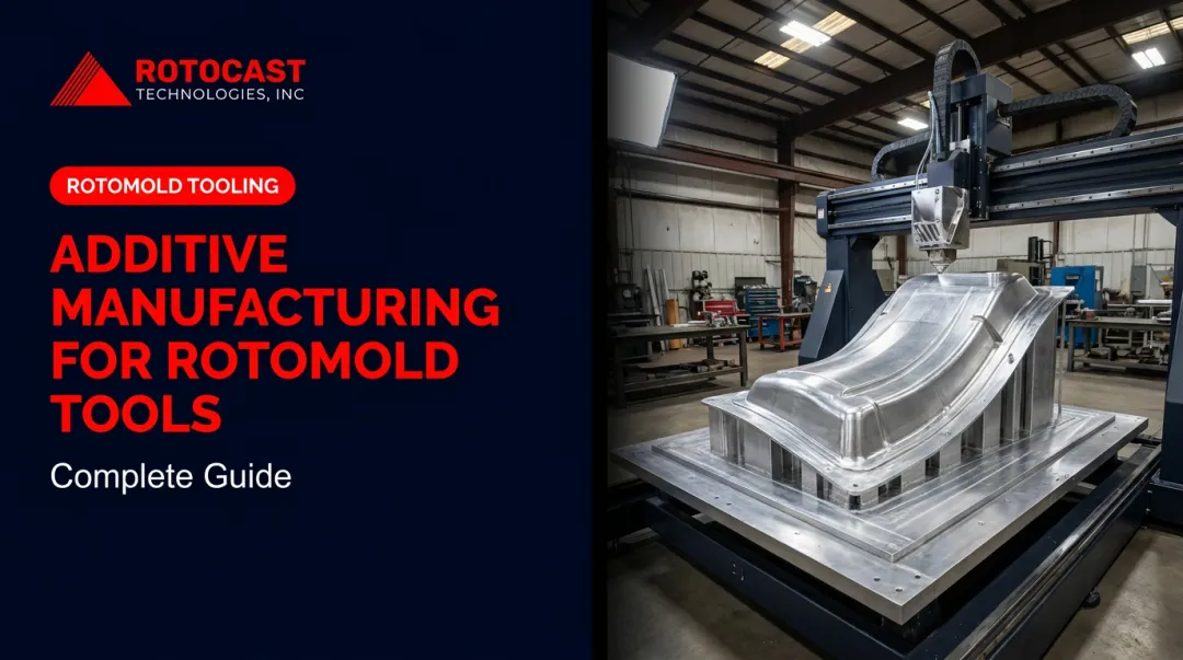
CNC machining improved dimensional accuracy compared with manual pattern making, allowing tooling tolerances in the thousandths of an inch. Rotocast uses a flexible approach — in-house wood pattern craftsmen for many projects, with CNC and foam pattern production available through partner pattern shops when geometry demands it. Each design is validated by an engineer before pattern production begins, and the Tooling Department specifically reviews wall thickness and parting line layout for optimal shutoff.
Melting, Pouring, and Solidification
Alloy quality and melt preparation directly determine casting density. Nearly 95% of surveyed aluminum metalcasters consistently use A356 for foundry work, and melt treatment — degassing, fluxing, and grain refinement — is where porosity is either prevented or locked in permanently.
Porosity matters in compression tooling because high-cycle fatigue life in A356-T6 is highly sensitive to microstructural inclusions and stress concentrations, including shrinkage porosity and entrapped oxides. A tool with internal porosity will develop stress concentration points under cyclic loading and fail earlier than a dense casting.
That porosity risk shapes alloy selection. Rotocast uses A356.2 grade aluminum: a higher-purity variant with stricter chemical limits and primary aluminum ingot composition. Compared to standard A356.0, A356.2 delivers greater elongation, higher strength, and measurably higher ductility — properties that matter in thin-walled molds subjected to repeated thermal cycling. Rotocast's foundrymen use sand casting with proprietary foundry tooling developed specifically for rotational mold production, with a focus on metal flow and fill over complex geometry.
Post-Cast Processing and Finishing
After shakeout and cleaning, casting blanks are dimensionally inspected before CNC time is committed. T6 heat treatment — standard for tooling-grade A356 applications — maximizes strength and hardness prior to machining. A356-T6 sand castings deliver tensile strength of approximately 37 ksi (255 MPa) and yield strength of ≥165 MPa.
The CNC machining stage brings the casting to final cavity tolerances, parting line fit, and interior surface geometry. Rotocast's finishing technicians then hand-polish cavities to the required level, with options including:
- Shot peened and sandblasted textures
- Acid etching
- Polished surfaces from light hand-sand to mirror polish
- Teflon® coating and specialty coatings
Because the outside surface of any rotomolded part is a direct mirror of the mold interior, any surface flaw in the mold reproduces on every part the tool ever runs.
Design Considerations for Aluminum Compression Tooling
Wall Thickness and Structural Integrity
Uniform wall thickness is the single most impactful design variable in aluminum compression tooling — particularly for rotational molds, where the mold wall is the only heat transfer path between the oven and the plastic resin charge.
Rotocast targets ¼" to 3/8" wall thickness for rotational molds. This range balances structural integrity against thermal performance: thick enough to resist distortion over thousands of cycles, thin enough to transfer heat rapidly and uniformly.
When walls vary significantly in thickness:
- Thicker sections heat more slowly, creating cold zones where resin consolidation lags
- Thinner sections overheat, producing surface defects and accelerating localized fatigue
- The ARM Design Guide states that uneven heat application is the predominant factor in wall-thickness variation in rotomolded parts, with commercial tolerance of ±20% and tighter optimization achievable to ±10%
Where geometry forces locally thin or thick sections, ribbing and gussets can maintain structural rigidity without adding bulk that disrupts heat transfer. Rotocast's Tooling Department reviews wall thickness and parting line layout for every project. An engineer validates each design before casting begins.
Draft Angles and Parting Line Placement
Aluminum foundry compression tooling involves a two-stage draft consideration that must be coordinated early:
- Casting draft — needed to release the pattern from the sand mold during casting
- Functional draft — needed in the compression cavity to release the finished molded part
These angles must work together. A functional cavity draft that conflicts with casting draft geometry creates costly machining problems after the casting is made.
Parting line location has downstream consequences for flash formation, part aesthetics, and tool assembly alignment. Poor parting line decisions made at the design stage cannot be corrected without significant rework after casting. Rotocast's pattern makers and foundry team review parting line placement collaboratively before pattern production starts — customers approve the design before metal is poured.
Interior Surface Quality
The interior cavity surface condition in aluminum compression tooling affects three production outcomes: part release, surface finish of the molded product, and cycle time. For rotational molds specifically, the mold interior must be free of blemishes because every imperfection transfers directly to the part surface.
The foundry process establishes the baseline interior surface condition. Alloy selection, pouring technique, and mold preparation all influence raw casting surface quality before any machining occurs. Rotocast's heritage in aluminum tire mold production — tools that demanded dense, high-surface-quality castings — carries directly into their rotational mold work.
Post-cast finishing options include:
- Standard sandblast texture for general production use
- Mirror polish for high-cosmetic-quality part surfaces
- Teflon coating for applications requiring enhanced part release
Why Aluminum? Key Material Advantages for Compression Tooling
Thermal Conductivity
Aluminum conducts heat four to six times faster than common tool steels — a gap that directly drives cycle time and part consistency:
| Material | Thermal Conductivity |
|---|---|
| 6061-T6 aluminum | 167 W/m·K |
| A356.0-T6 aluminum | 151 W/m·K |
| P20 mold steel | 41.5 W/m·K |
| 4140 alloy steel | 42.6 W/m·K |
| H13 tool steel | 25.1 W/m·K |
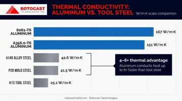
Sources: MatWeb A356.0-T6, MatWeb 6061-T6, Hudson Tool Steel P20
For compression and rotational molding, that faster heat-up and cool-down translates directly to shorter cycle times and more consistent part quality across a production run.
Weight and Machinability
Aluminum at ~2.70 g/cm³ weighs roughly one-third of steel at ~7.85 g/cm³. For large rotational molds, this weight difference matters in practice:
- Reduces press tonnage or machine arm load requirements
- Makes tool changes faster and physically safer
- Lowers shipping costs on large tool sets
Aluminum also CNC machines at higher speeds with lower tool wear than P20 or H13 steel, cutting finishing costs and shortening lead times compared to equivalent steel geometry.
Surface Treatability
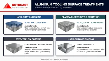
Aluminum compression tooling can be surface-treated to extend cavity wear life and improve part release:
- Hard-coat anodizing (Type III) — produces surface hardness of 60–70 Rockwell C and a dense oxide layer approximately 0.002" thick
- Plasma electrolytic oxidation (PEO) — ceramic oxide layer 20–45 microns at 500–2,000 HV
- PTFE/Teflon coating — provides quick-release finish, reducing demolding friction and extending surface life
- Hard chrome plating — hardness of 72 Rockwell C with a friction coefficient of 0.2 against steel
Treatment selection depends on the resin and production volume. Rotational molds running challenging part geometries typically specify Teflon coating for release; tools running abrasive resins or high annual cycles call for hard-coat anodizing. Rotocast applies both as standard finishing options on cast aluminum molds.
Applications of Aluminum Foundry Compression Tooling
Cast aluminum tooling serves a broad range of forming applications, with the specific design requirements varying by process:
- Rotational molding — thin-walled aluminum molds for hollow plastic products ranging from small components to 400-gallon containers; the low-pressure process and heat-transfer requirements are a natural match for cast aluminum
- SMC/BMC composite compression molding — ACMA identifies BMC and SMC as core compression molding materials for automotive panels, structural brackets, and enclosures; aluminum tooling suits short-to-medium production runs in these applications
- Urethane and vacuum forming — specialty aluminum castings for lower-pressure forming processes where aluminum's machinability and surface treatability are advantages
- Prototype and development tooling — aluminum's lower machining cost and faster lead time make it the default choice for prototype runs before committing to steel production tooling
Rotational molding is where cast aluminum's properties align most precisely with process demands. The ARM Design Guide notes that cast aluminum molds can vary wall thickness and incorporate cast-in heat fins to meet specific heat-transfer requirements — a level of thermal tuning that fabricated steel or machined billet tools cannot match.
Matching Tooling to Production Volume
That application fit extends to volume considerations. Aluminum compression tooling is well-suited to low-to-medium production volumes and prototype work.
For very high-pressure compression applications or extremely high cycle counts where hardness is the limiting factor, tool steel becomes the practical alternative. The specific threshold depends on compression pressure, resin type, and cycle frequency — worth discussing with your foundry partner before committing to an alloy.
How to Choose an Aluminum Foundry for Compression Tooling
Capability Integration
Prioritize foundries that perform pattern making, casting, and CNC machining under one roof. Each handoff between separate vendors introduces:
- Tolerance stack-up as drawings and physical parts transfer between facilities
- Scheduling gaps that extend lead time
- Accountability ambiguity when a dimension is out of spec
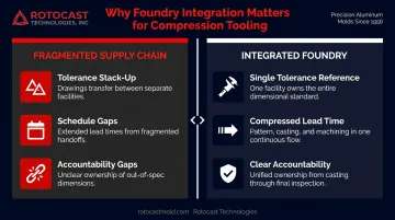
Ask prospective suppliers to map their end-to-end process and identify specifically where, if anywhere, work is subcontracted.
Quality Controls to Ask About
General aluminum foundries and tooling-grade foundries are not the same operation. For compression tooling specifically, ask about:
- Porosity testing methods (X-ray, dye penetrant)
- Melt treatment documentation (degassing, grain refinement practices)
- Heat treatment records for T6 temper
- Dimensional inspection protocols before and after CNC machining
- Surface quality standards for tooling-grade interior cavities
Experience and Track Record
Years of tooling-specific foundry work — not general casting experience — is the strongest predictor of performance. A foundry that casts automotive brackets and one that casts precision rotational molds operate at fundamentally different levels of process discipline.
That distinction matters when evaluating suppliers. Rotocast Technologies, based in Akron, Ohio, has 70 years of foundry heritage and a workforce averaging 16 years of specialty casting and mold manufacturing experience. Their proprietary sand casting process was developed specifically for rotational mold production, drawing on decades of aluminum tire mold manufacturing — a thin-wall casting application with some of the tightest dimensional and surface requirements in the industry. That depth of process-specific experience, combined with vertical integration from pattern making through final machining, is what separates purpose-built tooling foundries from general casting shops.
Frequently Asked Questions
What is the difference between aluminum and steel compression tooling?
Aluminum offers lower weight, faster thermal cycling, and lower machining cost, making it practical for low-to-medium volume production and prototype work. Steel provides higher surface hardness and withstands higher compression pressures and very high cycle counts where aluminum's lower hardness becomes a wear limitation.
What casting method is most commonly used for aluminum compression tooling?
Sand casting (including chemically bonded sand systems) remains the preferred method for large or geometrically complex compression tooling, with over six decades of proven use producing near-net-shape aluminum castings. Permanent mold casting suits smaller, simpler geometries where the tooling investment is justified by volume.
How long does aluminum compression tooling typically last?
Lifespan depends on compression pressure, alloy and heat treatment, surface treatments, and maintenance practices. Well-made A356.2-T6 aluminum rotational molds, supported by proper frame design and periodic refurbishment, routinely achieve thousands to tens of thousands of production cycles. Rotocast's repair and rebuild services can extend tool life significantly beyond the initial production run.
What aluminum alloys are best suited for compression tooling?
A356 (and its higher-purity A356.2 variant) is the most widely used foundry alloy for compression tooling, with T6 heat treatment maximizing strength and hardness. Alloy 319 suits permanent mold applications; 6061-T6 is standard for machined or wrought tooling. T6 temper is the benchmark heat treatment across all three.
Can aluminum compression tooling be repaired or modified after it is made?
Yes. Common options include TIG weld repair, cavity re-machining for dimensional correction, and re-application of surface treatments like Teflon coating. Rotocast's machine shop and finishing team provide mold rebuilding and refurbishment services to extend tool life without full replacement.
How does wall thickness uniformity affect compression tooling performance?
Inconsistent walls create thermal hot spots and cold zones during production cycles, resulting in uneven part cure or consolidation, extended cycle times, and localized stress buildup in the tooling. Over time, those stress concentrations accelerate fatigue failure , shortening tool life and increasing scrap rates.