Introduction
Specifying the wrong tolerance on an aluminum casting drawing is one of the most expensive mistakes in metal parts procurement — and it happens constantly. Engineers pull a DCTG grade from a competitor's print, apply die casting benchmarks to a sand-cast design, or write ±0.01 mm across the board without considering whether the process can actually deliver it.
The consequences run in both directions. Too loose, and parts fail at assembly. Too tight, and scrap rates climb, die costs balloon, and the foundry starts applying workarounds that compromise part integrity.
This guide covers:
- What aluminum casting tolerances actually mean and how they're graded
- How ISO 8062-3 DCTG grades and NADCA standards work in practice
- What each casting process realistically achieves dimensionally
- How to specify, measure, and validate tolerances without creating downstream problems
It also addresses the misinterpretations that consistently drive rework costs and supplier disputes.
Key Takeaways
- Casting tolerance is the total permissible dimensional variation from nominal, not an automatic ±value — ISO 8062-3 defines it as a full band
- ISO 8062-3 covers DCTG grades 1–16; NADCA sets separate benchmarks for aluminum high-pressure die casting
- Aluminum shrinks roughly 1.3% on cooling — mold cavities must be oversized, or finished castings will come up short
- As-cast tolerances run DCTG 4–7 for pressure die casting and DCTG 10–14 for hand sand casting; machining tightens critical features after
- Wall thickness always grades one DCTG coarser than linear dimensions — treating them the same is a common, costly mistake
What Casting Tolerances Mean in Aluminum Casting
Casting tolerance is the permissible variation between a part's nominal (design) dimension and its actual as-cast measurement. Under ISO 8062-3, tolerance values are expressed as total bands. A DCTG 7 tolerance of 1.10 mm on a 63–100 mm feature means the actual dimension may fall anywhere within a 1.10 mm window centered on nominal — ±0.55 mm on each side.
Three terms get conflated in casting specifications constantly:
- Tolerance — the allowable dimensional variation around nominal
- Allowance — a deliberate offset built into the pattern to compensate for shrinkage or provide machining stock; ISO 8062-3 covers machining allowance grades separately from DCTG
- Fit — how mating parts interact dimensionally; a design requirement, not a DCTG grade
Mixing them up produces drawings where machining stock is mistaken for tolerance band — meaning parts pass inspection but fail to machine to final geometry.
Linear vs. Geometric Tolerances
ISO 8062-3 governs two distinct tolerance types, and both apply to aluminum castings:
- Linear dimensional tolerances (DCTG) — govern length, diameter, hole spacing, and wall thickness
- Geometric casting tolerances (GCT) — govern form and orientation: flatness, straightness, concentricity, parallelism, and perpendicularity
These must be specified separately. A casting can hold tight DCTG linear tolerances while exhibiting significant flatness deviation — both matter for assembly performance.
Tolerances are also not a passive attribute of the metal. They function simultaneously as a design constraint, a process capability statement, and a quality acceptance criterion. Moving from DCTG 9 to DCTG 6 on a rotational mold cavity, for example, can require CNC finishing on surfaces that would otherwise ship as-cast — adding time and cost that should be built into the design phase, not discovered at inspection.
Factors That Influence Tolerances in Real-World Aluminum Casting
Shrinkage and Material Variables
Aluminum contracts during solidification. A commonly used pattern shrink allowance of approximately 1.3% means mold patterns must be deliberately oversized so finished castings meet nominal dimensions. Without that compensation, every linear dimension will be undersized.
The practical complication: actual shrinkage isn't fixed. A 2018 peer-reviewed sand casting study measured A356 shrinkage at 2.4%–2.84% and US 413 alloy at 1.9%–2.11% under experimental conditions — a meaningful spread.
Alloy composition, pouring temperature, and cooling rate all shift actual contraction away from the nominal allowance. A foundry that has poured thousands of A356.2 castings has empirical data on its actual shrinkage behavior, not just textbook estimates.
Tooling Variables
Tooling drives the majority of dimensional variation in production castings. Key factors:
- CNC-machined patterns establish tighter dimensional baselines than hand-formed wood patterns
- Draft angles (typically 1°–3° on external surfaces) add dimensional variation to feature heights when steeper than needed
- Metal dies hold dimensions more consistently than sand molds across repeated thermal cycles
- Non-uniform cooling channels cause differential contraction and warpage across the part
For aluminum sand-cast rotational molds, achieving uniform wall thickness demands close coordination between pattern design and foundry execution. At Rotocast Technologies, for example, pattern makers expand models to compensate for both aluminum and plastic shrink, and the Tooling Department validates wall thickness and parting line layout before casting begins — steps that catch fit problems before metal is ever poured.
Process Parameters
Even with correct tooling, process variables can shift a part outside tolerance:
- Pouring temperature controls fluidity and fill — too low, and the mold geometry won't fully reproduce
- Thick and thin sections cool at different rates, producing differential shrinkage across the same part
- Where metal enters and feeds (gating and risering) sets the solidification sequence and affects dimensional stability
Tolerance Standards for Aluminum Castings: ISO 8062-3 and NADCA
ISO 8062-3 DCTG Grades
ISO 8062-3 is the primary international standard for casting dimensional and geometrical tolerances, replacing ISO 8062:1994. It defines 16 linear dimensional casting tolerance grades — DCTG 1 (tightest) through DCTG 16 (loosest). Lower grade numbers mean tighter tolerances.
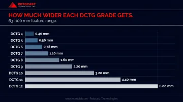
DCTG Reference Table — Total Tolerance Bands (mm)
| Nominal Dimension (mm) | DCTG 4 | DCTG 5 | DCTG 6 | DCTG 7 | DCTG 8 | DCTG 9 | DCTG 10 | DCTG 11 | DCTG 12 |
|---|---|---|---|---|---|---|---|---|---|
| ≤10 | 0.26 | 0.36 | 0.52 | 0.74 | 1.00 | 1.50 | 2.00 | 2.80 | 4.20 |
| >16–25 | 0.30 | 0.42 | 0.58 | 0.82 | 1.20 | 1.70 | 2.40 | 3.20 | 4.60 |
| >40–63 | 0.36 | 0.50 | 0.70 | 1.00 | 1.40 | 2.00 | 2.80 | 4.00 | 5.60 |
| >63–100 | 0.40 | 0.56 | 0.78 | 1.10 | 1.60 | 2.20 | 3.20 | 4.40 | 6.00 |
| >100–160 | 0.44 | 0.62 | 0.88 | 1.20 | 1.80 | 2.50 | 3.60 | 5.00 | 7.00 |
| >160–250 | 0.50 | 0.70 | 1.00 | 1.40 | 2.00 | 2.80 | 4.00 | 5.60 | 8.00 |
Selected rows shown; full table covers 16 dimension ranges. Source: ISO 8062-3:2007.
To put those numbers in context: a DCTG 5 tolerance on a 63–100 mm feature is 0.56 mm total (±0.28 mm bilaterally). A DCTG 11 tolerance on the same feature range is 5.00 mm total — nearly nine times wider.
Beyond linear dimensions, ISO 8062-3 also defines Geometrical Casting Tolerance Grades (GCTG 2–8, with GCTG 1 reserved). For aluminum pressure die casting, typical GCTG grades are 3–5, covering flatness, straightness, and concentricity.
The Wall Thickness Rule
Under ISO 8062-3, wall thickness tolerances are always one DCTG grade coarser than the general linear tolerance. A casting specified at DCTG 7 for external linear features holds wall thickness only to DCTG 8.
Why? Wall thickness depends on the relative positioning of core and cavity — two independent variables — rather than a single cavity dimension. That added variability is why section thickness is harder to control than external features.
Practical example: For a 3–6 mm wall at DCTG 8, the applicable tolerance from the ≤10 mm row is 1.00 mm total. That's ±0.50 mm on a wall that may nominally be only 4 mm thick — a significant proportion of the nominal dimension.
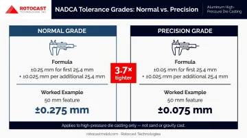
NADCA Standards for Aluminum Die Casting
Where ISO 8062-3 provides a process-agnostic framework, NADCA standards are tailored specifically to conventional high-pressure die casting. They are not applicable to sand or gravity cast aluminum.
| NADCA Grade | Linear Tolerance Formula |
|---|---|
| Normal | ±0.25 mm for first 25.4 mm + ±0.025 mm per additional 25.4 mm |
| Precision | ±0.05 mm for first 25.4 mm + ±0.025 mm per additional 25.4 mm |
For a 50 mm feature under Normal grade: ±0.25 mm + ±0.025 mm (for the remaining ~24.6 mm increment) = approximately ±0.275 mm total. Precision grade on the same feature yields roughly ±0.075 mm — about 3.7× tighter.
NADCA also defines separate tolerance classes for dimensions crossing the parting line, dimensions toward moving cores, and flatness — each with Normal and Precision variants.
Typical Tolerance Ranges for Aluminum Castings
The following ranges represent as-cast conditions before any secondary machining. Achievable tolerance within each process class varies by part size, geometry complexity, and foundry capability.
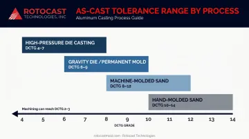
By Casting Process
| Process | ISO Annex A DCTG Range | Notes |
|---|---|---|
| High-pressure die casting | DCTG 4–7 | Tightest as-cast; DCTG 5 at 63–100 mm = 0.56 mm total |
| Gravity die / permanent mold | DCTG 6–9 | Lower fill pressure allows more thermal variation |
| Machine-molded sand | DCTG 8–12 | DCTG 11 at 100–160 mm = 5.00 mm total |
| Hand-molded sand | DCTG 10–14 | For large structural features without tight fit requirements |
Source: ISO 8062-3:2007 Annex A, light-metal alloys. ISO notes these grades are normally achievable only in long series or with fully developed production factors.
Sand Casting for Rotational Molds
Rotocast Technologies uses sand casting with proprietary foundry tooling for its aluminum rotational molds. This process targets the DCTG 8–12 range for external linear features. Wall thicknesses of ¼" to 3/8" (approximately 6–10 mm) are typical, held to the one-grade-coarser rule for section thickness.
Surface quality requirements for rotational molds are particularly stringent — the mold interior directly determines the outer surface of every plastic part produced from it. Dense, defect-free castings with consistent wall thickness take priority, with CNC machining reserved for critical interfaces such as parting lines and arm attachment points.
Secondary Machining
When as-cast tolerances are insufficient, machining can bring aluminum features to approximately DCTG 2–3 precision. The key discipline is restraint — specifying tight tolerances only where function demands it:
- Parting lines and sealing surfaces
- Pin and insert locations
- Arm attachment and frame-mounting interfaces
Blanket machining specifications drive up cost, extend lead time, and increase scrap without improving part function.
How Aluminum Casting Tolerances Are Specified, Measured, and Validated
Specification and Documentation
Two approaches work on engineering drawings:
- General tolerance note — references the applicable DCTG grade (e.g., "General casting tolerances per ISO 8062-3 DCTG 8") covering all non-called-out features
- Explicit callouts — bilateral tolerances or GD&T feature control frames on critical dimensions
The distinction between rated tolerance (what the standard says is achievable for the process) and proven tolerance (what First Article Inspection confirms for the specific part and tooling combination) matters for procurement. A DCTG grade on a drawing is a specification, not a performance guarantee until FAI confirms it.
Measurement and Verification
Measurement tools by application:
- Calipers and micrometers — rapid spot checks on accessible features
- CMMs (Coordinate Measuring Machines) — full-surface dimensional verification against CAD; typical measurement uncertainty of ±0.005 mm must be factored into acceptance decisions at tight tolerances
- 3D optical scanning — complex geometries and thin-walled features where contact probing is impractical
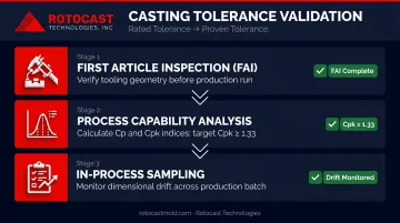
Once measurement tools confirm dimensional accuracy, statistical validation determines whether the process can hold those results consistently over a production run.
Statistical process validation:
- Confirm process capability with Cp and Cpk indices — a Cpk ≥ 1.33 indicates reliable tolerance control (per Bosch manufacturing guidance)
- Run First Article Inspection (FAI) to verify tooling geometry before full production begins
- Maintain in-process sampling to catch dimensional drift before it compounds across a batch
Common Misinterpretations of Aluminum Casting Tolerances
Three errors appear repeatedly in casting specifications — each generating avoidable cost.
1. Treating DCTG Grades as Automatic Guarantees
DCTG grades define what is achievable under appropriate process conditions. ISO 8062-3 Annex A explicitly states that listed grades are normally achievable only for long series or with fully developed production factors. Short-run or less mature processes may require coarser grades.
A DCTG grade on a drawing is a requirement. Whether the foundry can meet it depends on part geometry, tooling quality, and process maturity.
2. Ignoring the Linear vs. Wall Thickness Distinction
Wall thickness depends on the relative positioning of core and cavity — two independent variables. Applying the same DCTG grade to wall thickness and external linear features creates an unachievable specification. The one-grade-coarser rule exists for a reason: include it on drawings or expect non-conformances.
3. Applying Die Casting Tolerances to Sand or Gravity Castings
Each process occupies a distinct DCTG range. NADCA Normal and Precision grades apply only to high-pressure die castings. Specifying DCTG 4 or 5 on a sand-cast aluminum part without machining that feature is not achievable as-cast.
Process selection and tolerance specification must be resolved together at the design stage, before the casting method is locked — not after.
Conclusion
Aluminum casting tolerances are a governing design parameter, not a detail to sort out at the drawing check stage. Matching specified tolerance to casting process, part geometry, functional requirement, and foundry capability is the discipline that determines whether parts move through production cleanly or accumulate rework, scrap, and secondary machining costs at every stage.
ISO 8062-3 DCTG grades and NADCA benchmarks provide the framework. Whether those grades translate into repeatable as-cast accuracy depends entirely on the foundry's actual process capability — not what it accepts on paper.
Rotocast Technologies has been producing aluminum cast rotational molds since 1956. The in-house foundry has spent decades refining sand casting processes specifically for the thin-wall dimensional and surface quality demands of the rotational molding industry, with a workforce averaging 16 years of specialty casting experience. For projects where tolerance specification and foundry capability need to be aligned from the start, contact Rotocast at sales@rotocastmold.com or 330.203.2335.
Frequently Asked Questions
What are typical casting wall thickness tolerances?
Wall thickness tolerances are held to one DCTG grade coarser than standard linear tolerances under ISO 8062-3. For a casting specified at DCTG 7, wall thickness is controlled to DCTG 8. On a 3–6 mm wall at DCTG 8, this means a total tolerance band of 1.00 mm.
What does a ±0.01 mm casting tolerance mean?
It means the actual dimension must fall within 0.01 mm above or below nominal — so a 50 mm feature must measure between 49.99 and 50.01 mm. This is approximately DCTG 2–3 and is not achievable as-cast for aluminum; it requires secondary machining to hold reliably.
What does "CT" tolerance mean for castings?
CT (Casting Tolerance) is the grade designation from the original ISO 8062:1994 standard. The current ISO 8062-3 replaced CT grades with DCTG for dimensional tolerances and separately defined GCTG grades for geometric tolerances. Grade numbering is similar (CT 4–6 corresponds roughly to DCTG 4–6), but the newer system provides cleaner separation of dimensional and geometric controls.
What is F7 tolerance for castings?
F7 is not a casting tolerance designation — it is an ISO 286 fit classification for machined holes and shafts (a clearance fit). F7 may apply to a bored or machined feature on a cast part, but the casting itself is specified using DCTG or NADCA grades. Applying shaft/hole fit designations to as-cast surfaces is a specification error; those designations govern machined interfaces only.
How does aluminum's shrinkage rate affect casting tolerances?
Pattern shrink allowance for aluminum is approximately 1.3%, meaning mold cavities must be oversized by that amount. If shrinkage compensation is wrong, all linear dimensions shift undersized, effectively moving the entire tolerance window. Alloy and process variation cause actual shrinkage to differ from nominal, making foundry experience with the specific alloy critical for dimensional predictability.
When should precision tolerances be specified over standard tolerances?
Precision tolerances — NADCA Precision grade or DCTG 4 and below — should apply only to features where fit, sealing, or mechanical alignment genuinely requires it. Applying them across all features drives up die cost, cycle time, and scrap rates — specify a general DCTG grade for the drawing and call out tighter tolerances only on critical functional interfaces.