This guide gives you a practical reference for minimum wall thickness in aluminum sand casting, the design rules that work alongside it, and the defects you need to plan around from the start.
Key Takeaways
- 3mm (approximately 3/16") is the standard starting point for aluminum sand casting wall thickness — not an absolute minimum
- Actual achievable minimums depend on alloy, section length, part size, and foundry process
- No-bake processes consistently outperform green sand for thin, uniform walls — process choice matters as much as design
- Draft angles, corner radii, and section transitions all determine whether thin walls are castable — get one wrong and the others won't save you
- Heavy isolated sections cause as many problems as walls that are too thin — both need to be addressed together
What Is the Minimum Wall Thickness for Aluminum Sand Casting?
The Manufacturing Network's sand casting buyer's guide lists 3mm as the typical minimum for light alloys, and Sure Cast Foundry cites 3/16" as a conservative rule of thumb for production sand casting. The American Foundry Society notes that green sand processes can achieve walls as thin as 0.09" under the right conditions — though that represents capability under suitable precautions, not a standard design target.
Why does this number exist? Aluminum loses heat rapidly. In thin sections, the metal can solidify before the mold cavity is fully filled, producing an incomplete casting called a misrun. The thinner the section, the faster it freezes, and the harder it is to maintain adequate metal flow across the full geometry.
How Part Size Affects the Minimum
The achievable minimum isn't one number — it scales with the part:
| Part Category | Approximate Wall Thickness Range |
|---|---|
| Small/localized sections | ~2.5–3mm possible with process optimization |
| Standard production parts | 3–5mm typical design target |
| Large parts (longer flow paths) | 5–6mm+ to maintain fill |
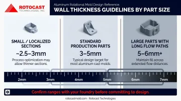
These ranges should be confirmed with your foundry before committing to a design. Longer, more extended thin sections need more thickness than small local features at the same nominal dimension.
Aluminum vs. Ferrous Alloys
Aluminum's relatively high fluidity is why its minimum benchmark sits around 3mm, while ferrous alloys typically require 5–6mm minimum sections. For applications where thin walls are a design priority, aluminum is the clear choice.
That fluidity advantage becomes critical in rotomolding applications, where uniform wall thickness directly controls heat transfer to the plastic resin. Rotocast Technologies has developed a proprietary casting process that achieves walls in the ¼" to 3/8" range, meeting the surface quality and density that rotomolding demands.
Their foundry experience producing aluminum tire molds provided the technical foundation for this capability.
Design Factors That Directly Impact Minimum Wall Thickness
Wall thickness doesn't exist in isolation. Several design features directly affect whether a thin wall is achievable — and whether it survives the casting process without defects.
Draft Angles
Draft angles of 1–3 degrees are required for green sand casting to release the pattern from the mold without tearing or distorting the sand. Without adequate draft, foundries add thickness as a buffer against mold damage — which defeats the purpose of thin-wall design.
- Ideal: 3 degrees
- Practical minimum: 1 degree (only when agreed with the foundry)
- Deep or internal features require more draft than shallow exterior faces
Corner Radii
Sharp corners concentrate heat and stress. The Manufacturing Network guide recommends internal radii of 1 to 1.25 times the wall thickness. As a practical minimum, 3mm (approximately 1/8") is a practical starting point for internal corners.
External radii should be sized proportionally. Leaving corners sharp creates localized thick spots at junctions, leading to shrinkage voids in sections you've already worked to keep thin.
Section Transitions and Thickness Uniformity
Abrupt thickness changes are one of the most common sources of casting defects. The principle to follow:
- Avoid section changes greater than 2:1 without a transition
- When a transition is unavoidable, taper gradually — a 1:4 ratio is the common design rule
- Thin sections solidify first; if they surround a heavy section, they cut off the feed metal supply to that heavier area
Bosses, Ribs, and Web Junctions
The same logic applies at junctions. T- and X-junctions where ribs or bosses meet the main wall create local material accumulation that behaves like an isolated heavy section. Follow these rules:
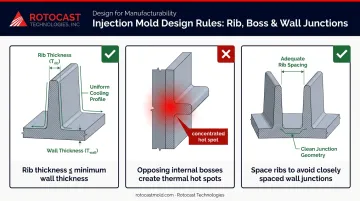
- Ribs and webs should match the minimum thickness of the main wall (0.10" is a common engineering reference for aluminum)
- Never place an internal boss directly opposite another internal feature on the same wall. The combined material at that point creates a concentrated hot spot that resists proper feeding.
- Space ribs so they don't create a series of closely spaced junctions that collectively function as a thick zone
Parting Line Placement
For aluminum (a lower-density alloy), position the parting line so heavier sections are fed from above. This allows gravity and riser pressure to maintain feed metal supply as the casting solidifies.
Defects Caused by Improper Wall Thickness and How to Prevent Them
Misruns and Cold Shuts
Both result from metal that cools too quickly during fill:
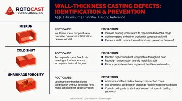
- Misrun: Metal freezes before reaching the mold wall, leaving an incomplete section with rounded edges
- Cold shut: Two metal streams meet but fail to fuse, leaving a visible surface seam
Prevention options include increasing wall thickness, selecting a higher-fluidity alloy, raising pouring temperature, or improving gating to increase metal velocity. Thin walls are the most common root cause, but poor gating can trigger these defects even in adequately thick sections.
Shrinkage Porosity in Isolated Heavy Sections
When thin walls surround a thick boss or heavy local section, the thin walls solidify first and cut off the feed metal supply. The heavier section continues cooling and contracts with no feed metal available, creating internal voids.
Solutions:
- Redesign to eliminate isolated masses where possible
- Use chills to accelerate solidification in the heavy section
- Adjust riser and feeder placement to maintain feed access longer
According to Foseco's casting defect guidance, feeding systems and exothermic sleeves are the primary process-side tools for managing shrinkage in isolated sections.
Hot Tearing at Sharp Transitions
Abrupt thickness changes create thermal stress concentrations as the casting cools unevenly, producing ribbon-like cracks or tears along the stressed zone.
Primary prevention methods:
- Add fillets and tapers at transitions to distribute the stress load
- Use a more collapsible sand mix — a mold that resists contraction contributes directly to tearing
Gas Porosity
Hydrogen absorbed from moisture in the mold environment forms bubbles as aluminum cools. Thin walls with turbulent fill paths are especially prone to this defect because there's less material to mask the defect. Controls include:
- Rotary degassing with inert gas before pouring
- Proper mold venting
- Covering fluxes to limit hydrogen pickup
When prevention measures fall short, vacuum resin impregnation can seal leak paths in finished castings without affecting part dimensions — a practical fallback for non-structural porosity.
How Sand Type Affects Minimum Achievable Wall Thickness
The sand system your foundry uses determines both how thin your walls can be and how consistently those dimensions hold across the part. The two most common options for aluminum casting — green sand and no-bake — differ significantly in mold strength and thin-section capability.
Green Sand vs. No-Bake (Chemically Bonded) Sand
| Factor | Green Sand | No-Bake / Chemically Bonded |
|---|---|---|
| Mold strength | Lower — can deform under metal pressure | Higher — holds detail under pouring pressure |
| Thin section capability | More challenging for fine or elongated sections | Better suited to thin, consistent walls |
| Surface finish | 250–1,000 microin RMS | Generally improved over green sand |
| Best application | Cost-sensitive, higher volume, standard tolerances | Complex geometry, tighter tolerances, thinner walls |
| Cost | Lower | Higher |
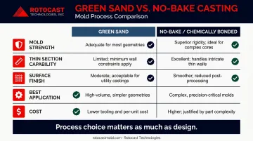
The key difference is what happens under pouring pressure. Green sand molds can shift or erode at thin sections, causing dimensional variation. No-bake molds cure rigid before metal enters, maintaining geometry through the pour.
Practical Process Selection
Choose green sand when:
- Volume justifies the tooling setup
- Tolerances are standard, not tight
- Wall sections stay above 4–5mm
Choose no-bake when:
- Wall sections approach the 3mm range
- Core work or complex internal geometry is involved
- Surface finish and dimensional consistency are critical
Confirm the foundry's available process before finalizing wall dimensions. A green sand shop quoting a 3mm section may deliver variable results — what they can pour and what they can pour consistently are two different things.
Tolerances and Surface Finish: What to Realistically Expect
Dimensional Tolerances
According to AFS/Casting Source green sand data, practical small green sand tolerances run ±0.06", with ±0.03" possible at added cost and rejection risk. LB Foundry cites ±0.030" up to 6", plus ±0.003" per inch over 6", with parting-plane adders of ±0.020" to ±0.060" depending on projected area.
For drawing specification, ISO 8062-3 defines casting tolerance grades DCTG 1–DCTG 16 and is the governing standard. Under ISO 8062-3, wall thickness tolerances run one grade coarser than general linear tolerances. Design critical sections with that gap built in — it's easy to miss on first pass.
Here's a quick reference for common green sand aluminum tolerances:
| Tolerance Type | Typical Value | Notes |
|---|---|---|
| Standard green sand | ±0.06" | Practical baseline for small castings |
| Precision green sand | ±0.03" | Higher cost, elevated rejection risk |
| Linear (up to 6") | ±0.030" | Per LB Foundry data |
| Linear (over 6") | +±0.003"/inch | Added incrementally beyond 6" |
| Parting plane adder | ±0.020"–±0.060" | Depends on projected area |
| Wall thickness grade | One grade coarser | Per ISO 8062-3 vs. general linear |
Surface Finish and Machining Allowance
As-cast surface finish for aluminum sand casting ranges from 3.2–25.0 Ra μm (Manufacturing Network). No-bake processes improve on green sand qualitatively, though the exact improvement varies by foundry and geometry.
Build in a machining allowance of 1.5–6mm wherever post-cast machining is required. This adds to the nominal wall thickness in the design: a 3mm nominal wall with a 2mm machined surface needs to start at 5mm in the casting.
Shrinkage Allowance
LB Foundry cites aluminum shrinkage at approximately 5/32" per foot (~1.3%). Foundries build this into the pattern dimensions, so the drawing reflects the finished part, not the pattern. Designers don't need to calculate it, but understanding it explains why pattern dimensions don't match finished part dimensions.
Frequently Asked Questions
What is the minimum wall thickness for aluminum sand casting?
The standard industry starting point is 3mm (approximately 3/16"). The actual achievable minimum varies based on alloy, section geometry, section length, and the foundry's specific process capabilities — some operations can achieve thinner sections, but this requires direct confirmation with the foundry.
How thin can aluminum be cast?
With standard sand casting, small or localized sections can approach 3mm; AFS sources note green sand capability as low as 0.09" under specific conditions. No-bake processes and experienced foundries can push closer to that limit — but it requires early collaboration and process-specific validation.
What tolerances can you expect from aluminum sand casting?
Practical tolerances for small green sand castings run ±0.03" to ±0.06", with parting line and core joint adders beyond that. For formal drawing requirements, reference ISO 8062-3 tolerance grades. Confirm achievable tolerances with your foundry before finalizing drawings.
Can aluminum be sand cast?
Yes — aluminum is one of the most commonly sand cast metals. Its high fluidity and low melting point make it well-suited to both green sand and no-bake processes across a wide range of part sizes and geometries.
What is the ideal wall thickness for an aluminum sand casting?
For most standard parts, 4–6mm balances structural requirements with reliable castability. The goal is uniform thickness throughout the part — consistent walls solidify evenly and reduce both misrun and shrinkage risks.
Is sand casting better than die casting for aluminum?
Neither is universally better. Sand casting offers lower tooling cost, greater design flexibility, and suits lower-volume production of larger parts. Die casting holds tighter tolerances (NADCA standard: ±0.010" for the first inch) and achieves thinner walls (down to ~0.040"), making it the better fit for high-volume runs. Choose based on your part size, production volume, and tolerance requirements.