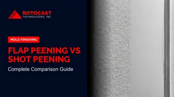
Both flap peening and shot peening introduce compressive residual stresses into metal surfaces to extend fatigue life — but they're built for entirely different operational realities. Pick the wrong one and you're looking at compliance failures, unnecessary downtime, or parts that don't get the treatment they actually need.
This guide breaks down the mechanism, process control, standards, real-world use cases, and decision criteria for both methods — so you can make the right call the first time.
Key Takeaways
- Flap peening (rotary/flapper peening) uses tungsten carbide balls bonded to a Kevlar flap rotating at controlled RPM — portable, manual, ideal for localized repair
- Shot peening propels spherical media at 30–100 m/s via compressed air or centrifugal blast wheel; best suited for automated, high-volume, production-scale treatment
- Both create compressive residual stress to improve fatigue life; they differ in scale, control, cost, and accessibility
- Flap peening is governed by SAE AMS2590; shot peening by SAE AMS2430, and both fall under Nadcap audit requirements
- Choose flap peening for in-service repair and confined areas; choose shot peening for consistent, large-area production treatment
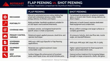
Flap Peening vs Shot Peening: Quick Comparison
| Factor | Flap Peening | Shot Peening |
|---|---|---|
| Mechanism | Rotating Kevlar flap with bonded tungsten carbide balls; centrifugal force drives impact | Spherical media propelled at 30–100 m/s via air nozzle or blast wheel |
| Portability | Handheld, compact — operable on installed components | Requires enclosed blast cabinet or dedicated machine |
| Coverage Area | Small, localized zones; holes ≥ ½" diameter | Large, uniform surfaces with high throughput |
| Primary Control Variable | RPM | Almen intensity, coverage, media flow |
| Governing Standard | SAE AMS2590 | SAE AMS2430, SAE J443 |
| Nadcap Audit Criteria | AC7117/4 | AC7117 |
| Equipment Cost | Low | High capital cost; lower per-part cost at scale |
| Best Application | MRO repair, post-blend re-peening, field use | Production components, fatigue-critical parts |
What Is Flap Peening?
What Is Flap Peening?
Mechanism and Origins
Flap peening — also called rotary peening or flapper peening — was developed by 3M for the U.S. Army in the 1960s, specifically to re-peen helicopter components during the Vietnam War without removing them from service.
The core problem it solved then is the same one it solves now: how do you restore compressive residual stress on an installed component without disassembling the aircraft and shipping parts to a peening shop?
The tool works by rotating a Kevlar flap — with tungsten carbide bearing balls (approximately 0.0330" diameter) bonded to its surface — at controlled RPM via a die grinder. Centrifugal force propels those balls into the part surface repeatedly, cold-working the metal and driving compressive residual stress into the surface layer.
Process Control and Almen Verification
RPM is the primary process variable. Operators set parameters using Almen intensity vs. RPM saturation curves specific to the flap assembly in use. Intensity verification still uses Almen strips — but with a critical difference: a magnetic Almen fixture replaces the standard screw-down block. Per SAE AMS2590, conversion of arc-height values using the magnetic holder is required for intensity determination. Typical flap peening intensity ranges from 0.008" to 0.015" A.
One persistent operational challenge: intensity consistency across multiple operators and varying air pressure conditions has historically been difficult to maintain. Closed-loop RPM controllers — like Shockform's FlapSpeed PRO — were developed specifically to address this, maintaining controlled RPM regardless of operator technique or air supply fluctuation.
Core Benefits for MRO Operations
- No disassembly required — treat components in-service, on-aircraft
- Clean process — no loose shot media to manage or contain
- Small-area access — reaches holes as small as ½" diameter (L/D ≥ 2)
- Eliminates transport — avoids masking, hardware removal, and round-trip shipping to a peening facility
- Faster repair turnaround — in-house emergency repair capability returns aircraft to service more quickly
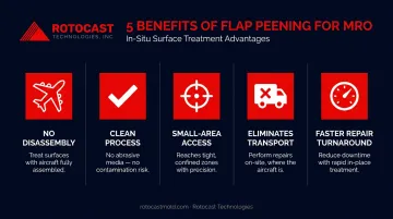
For airlines and defense MRO operations where fleet availability is measured in hours, each of those factors directly affects aircraft availability. For compliance, flap peening falls under Nadcap audit requirements per AC7117/4 criteria, which requires documented and controlled RPM verification.
What Is Shot Peening?
Mechanism and Process Control
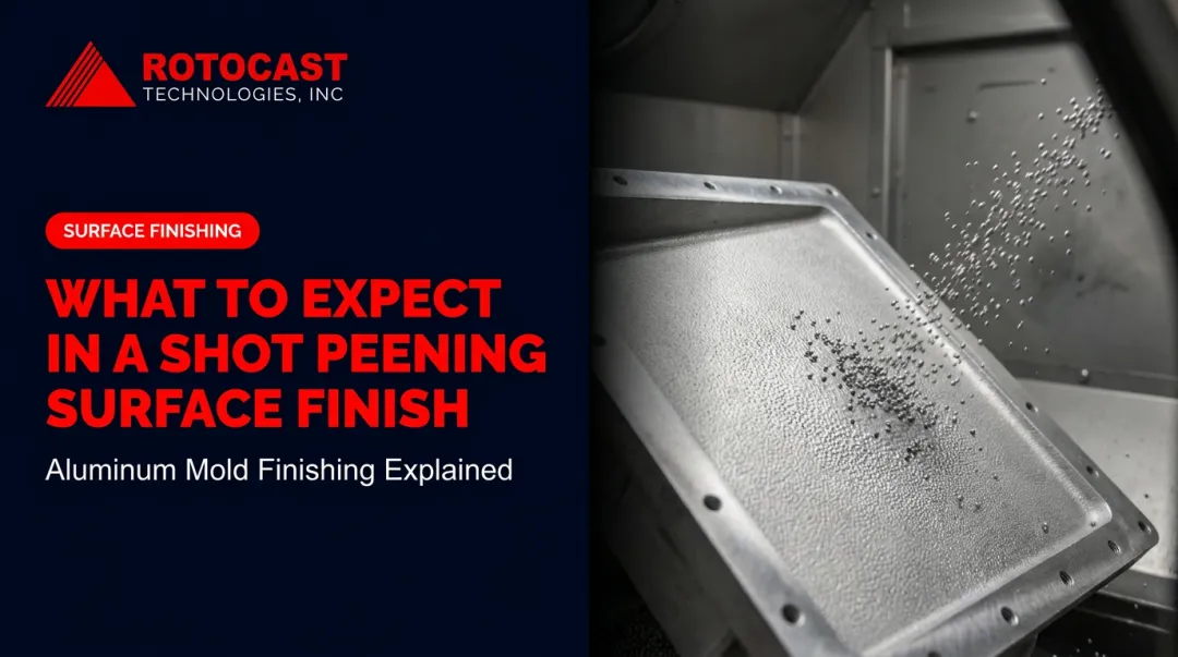
Shot peening is a controlled cold-working process — not a cleaning process. Where shot blasting removes surface contaminants, shot peening mechanically strengthens the surface layer by projecting spherical media at high velocity, creating small indentations that compress the metal and convert tensile residual stress into compressive residual stress.
Media strikes the surface at 30 to 100 m/s, with precise control over:
- Almen intensity — measured via arc height on standardized test strips (SAE J443)
- Coverage percentage — aerospace specifications typically require 100% visual coverage
- Media type, size, and hardness — matched to component material and required intensity
- Exposure time and velocity, monitored via real-time feedback in automated systems
Two delivery methods exist: air blast nozzles for targeted, precision work on complex geometries, and centrifugal blast wheels for high-volume throughput on uniform surfaces.
Shot Media Selection
| Media Type | Best For |
|---|---|
| Cast steel (45–52 HRC) | General-purpose ferrous components |
| High-hardness steel (55–62 HRC) | High-strength steels |
| Conditioned cut wire | Consistent hardness, no fragmentation, minimal contamination |
| Glass beads | Delicate parts, sharp thread radii, very low intensities; avoids iron contamination |
| Ceramic | Non-ferrous metals; recognized spherical media for aluminum and titanium |
Fatigue Life Impact
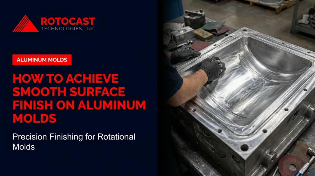
At Rotocast Technologies, shot peening is one of several in-house finishing options — alongside sandblasting, acid etching, and hand polishing — applied to A356.2 aluminum molds. Because the mold cavity surface directly mirrors the finished plastic part, the finishing choice has downstream quality implications for every production run.
Flap Peening vs Shot Peening: Which Should You Choose?
Key Decision Factors
Before committing to either method, work through these questions:
- Is the component installed in-service or available for shop processing?
- What is the surface area being treated — small localized zone or full component surface?
- Can blast equipment physically access the area?
- Is this a one-off repair or a repeating production operation?
- What compliance documentation is required?
Choose Flap Peening When:
- A component has been blended to remove surface damage and needs compressive stress restored in that specific zone
- The part cannot be removed from service or transported to a peening facility
- The treatment area is a small hole (≥ ½" diameter), a confined geometry, or a post-repair patch
- You need Nadcap-compliant MRO repair without shop-scale equipment
- Speed of return to service is the priority metric
Choose Shot Peening When:
- Treating large or uniform surfaces on new production components
- High-volume throughput is required across a production batch
- Tighter automated process control and documentation are needed for aerospace or automotive qualification
- The component is a fatigue-critical part (gears, springs, compressor blades, landing gear) being processed before first deployment
- Traceability and repeatability over thousands of parts must be demonstrated
A Note on Complementary Use
In practice, these two methods frequently work together in sequence. A turbine component may receive full shot peening at production, then require localized flap peening years later after a maintenance blend removes surface damage. Planning for both the manufacturing phase and the in-service repair phase gives you the most complete peening program.
Real-World Examples
Flap Peening: Aluminum Airframe Repair
A 2011 technical study on controlled rotary flap peening addressed repair of lower wing skins made from 7475-T7351 aluminum — a common scenario where surface damage is blended out and the compressive stress layer must be restored. Results from the study documented:
- Surface residual stress of -195 MPa
- Peak compressive stress of -286 MPa at 0.12 mm depth
- Fatigue-life improvement factor of 3 or better compared to the unpeened condition
- Surface finish 40% smoother than conventional peening with ASH230 shot
The repair was achievable without removing the wing skin from the aircraft, and the resulting fatigue performance met or exceeded what conventional shop peening would have delivered.
Shot Peening: Production Component Life Extension
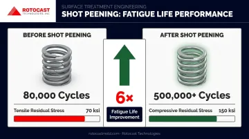
Curtiss-Wright's documented production data on compression springs demonstrates the commercial case for shot peening clearly. Shifting residual stress from tensile to compressive — 70 ksi tensile to 150 ksi compressive — extended component fatigue life from 80,000 cycles to over 500,000 cycles without failure. For valve train or transmission springs, that improvement shifts shot peening from a finishing option to a warranty-risk management decision.
The same logic applies in turbomachinery. HP compressor rotors going from 6,000 to 16,000 cycles after shot peening gives OEMs a clear lever: add shot peening to the production sequence and reduce overhaul frequency without redesigning the component.
Conclusion
Neither process is universally superior. Flap peening delivers portability and precision where shop equipment can't go; shot peening delivers consistency and throughput where production volume demands it.
For manufacturers and MRO teams, the decision comes down to two things: where the component is (in-service vs. production line) and how much surface area needs treatment. Match those two factors to the right method and you avoid over-engineering the process or under-treating the surface.
For rotational molders specifying mold surface finishes — including shot peen, sandblast, acid etch, and mirror polish — Rotocast Technologies applies these finishes in-house as part of complete aluminum cast mold production. Reach their team at sales@rotocastmold.com or 330-203-2335.
Frequently Asked Questions
What is the difference between flap peening and shot peening?
Flap peening uses a rotating Kevlar flap with bonded tungsten carbide balls to treat small, localized areas portably (governed by AMS2590). Shot peening propels spherical media at high velocity via compressed air or a blast wheel for large-area, high-volume treatment (governed by AMS2430). Both create compressive residual stress — the difference is scale, method, and where each is physically practical.
What is the purpose of shot peening?
Shot peening introduces compressive residual stress into a component's surface layer, converting tensile stress to prevent crack initiation and propagation. This extends fatigue life and improves resistance to stress corrosion cracking in components like gears, springs, turbine blades, and landing gear.
When should you use flap peening instead of shot peening?
Use flap peening when a component can't be removed from service, when treating a localized post-blend repair zone, or when accessing confined areas that blast nozzles can't reach. It's the standard for MRO and in-field aerospace repair where portability and fast return to service are the priority.
Can flap peening achieve the same Almen intensity as shot peening?
Flap peening typically achieves intensity in the 0.008"–0.015" A range, controlled through RPM. It requires correlation between standard Almen arc height readings and magnetic roto peen fixture readings per AMS2590. Intensity range and repeatability are narrower than automated shot peening equipment delivers across a production batch.
What standards govern flap peening and shot peening?
Shot peening is governed by SAE AMS2430 and SAE J443, while flap peening is governed by SAE AMS2590. Both are subject to Nadcap audit requirements in aerospace applications — AC7117/4 for flapper peening specifically — which mandate controlled and documented RPM or intensity verification throughout the process.
What media is used in flap peening vs shot peening?
Flap peening uses tungsten carbide bearing balls (~0.0330" diameter) bonded to a Kevlar flap. Shot peening draws from a wider range: cast steel shot, conditioned cut wire, glass beads, or ceramic beads — chosen based on component material, required intensity, and contamination sensitivity.