This matters beyond coating shops. For rotational mold producers, the interior Ra of an aluminum mold is a direct functional specification: whatever texture exists on the mold cavity surface transfers to every plastic part produced from it. Getting Ra wrong at the mold stage means getting it wrong on every part, indefinitely.
This guide covers what Ra actually means on sandblasted aluminum, what process variables control it, how to specify and measure it correctly, and what happens when it's wrong.
Key Takeaways
- Ra (Roughness Average) is the arithmetic mean of surface height deviations from a mean line, measured in µm or µin (per ASME B46.1 / ISO 4287)
- Sandblasted aluminum Ra is not fixed by media type alone — grit size, pressure, standoff, and alloy all interact to shift the result
- Typical sandblasted aluminum Ra falls roughly 1.6–6.3 µm (63–250 µin), with angular media producing higher values than spherical media
- Wrong Ra causes real failures: over-blasting produces uneven coating coverage; under-blasting produces adhesion failures
- Ra must be measured with a contact profilometer at the correct cutoff length — visual comparators aren't sufficient for acceptance decisions
What Ra Surface Finish Means in Sandblasted Aluminum
The Technical Definition
ASME B46.1-2009 defines Ra as the arithmetic average of the absolute values of profile departures from the mean line within a sampling length. In plain terms: measure the vertical distance from every point on the surface profile to the mean line, take the absolute values, and average them. The result is a single number that summarizes the overall texture amplitude.
Mitutoyo's surface roughness guide notes that Ra is the most commonly used roughness parameter worldwide — it's easy to measure and repeatable. Its limitation is that it averages out extreme peaks and valleys, which is why you may also encounter Rz on drawings.
Ra vs. Rz: When Each Applies
| Parameter | What It Measures | Best Used For |
|---|---|---|
| Ra | Arithmetic mean of all profile deviations | General texture specification, drawing callouts |
| Rz (ISO) | Mean of five highest peak-to-valley depths across the evaluation length | Applications where individual peaks affect sealing, corrosion, or release |
| Rz (ASME) | Ten-point height — different from ISO Rz | Rarely recommended; don't use without stating the convention |
One important caution from ASME B46.1: ASME's own Rz definition differs from ISO's. Always state which standard applies when specifying Rz, or disputes between supplier and buyer are almost guaranteed.
For most sandblasted aluminum specs, Ra is the primary callout. Rz is worth adding in critical applications — anodizing prep, mold release surfaces — where extreme peaks would cause problems that the Ra average obscures.
Physical Meaning at Different Ra Levels
Understanding Ra in practical terms means knowing what each range produces on the surface. A low Ra (around 1.6 µm) describes a fine, relatively uniform texture with shallow peaks. A high Ra (6.3 µm) describes an aggressive, open anchor profile. Each range serves a specific purpose:
- Low Ra (1.6–2.5 µm): Cosmetic surfaces, pre-anodizing prep, tight-tolerance parts
- Mid Ra (2.5–4.0 µm): General coating prep, paint adhesion
- High Ra (4.0–6.3 µm): Powder coating, adhesive bonding, maximum mechanical anchor
Ra in Rotational Mold Tooling
For aluminum rotational molds, the interior cavity Ra is a functional specification, not an aesthetic one. The outside surface of every rotationally molded plastic part is a direct mirror of the mold interior — so the mold surface finish becomes the part surface finish.
A mold cavity blasted to 4.0 µm Ra produces parts with a 4.0 µm Ra exterior, consistently across every production cycle. Specifying the mold surface finish correctly at the design stage is the only opportunity to get this right before production begins.
Key Factors That Determine Ra When Sandblasting Aluminum
Unlike machined surfaces where Ra is governed primarily by tool geometry and feed rate, sandblasted Ra is the product of several interacting variables. Change one without adjusting others and the Ra outcome shifts — sometimes significantly.
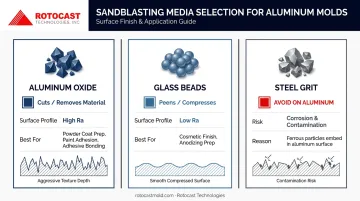
Media Type and Hardness
Media selection has the largest single influence on Ra outcome:
- Aluminum oxide — angular, hard abrasive that cuts into the aluminum surface. Produces a higher Ra with an open anchor profile suited to powder coating, paint, and adhesive bonding. Contamination risk is low since it's chemically compatible with aluminum
- Glass beads — spherical media that peens rather than cuts. Produces a lower Ra with a satin, matte appearance. Preferred for cosmetic surfaces and anodizing prep
- Steel grit — should be avoided on aluminum entirely. Kramer Industries notes that steel grit leaves a mild-steel film on aluminum surfaces, causing rust, staining, and discoloration. Galvanic corrosion risk follows
The key distinction is cutting vs. peening. Angular media removes material and opens the surface; spherical media compresses and smooths it. Match the mechanism to what the finished surface needs to do — bonding and coating applications need that open anchor profile, while cosmetic or anodized finishes benefit from the tighter, compressed texture glass beads produce.
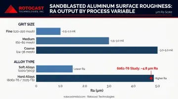
Grit Size and Media Condition
Kramer's aluminum oxide profile data illustrates the grit-to-profile relationship clearly:
| Grit Range | Approximate Profile Depth |
|---|---|
| 120–220 mesh (fine) | ~0.5–1.0 mil |
| 60–80 mesh (medium) | ~1.5–3.0 mil |
| 24–36 mesh (coarse) | ~3.0–5.0 mil |
Finer grit = less material removed per impact = smoother Ra. But media condition matters just as much as initial grit size. Media that has broken down from repeated reuse develops a wider particle size distribution — some particles are still full-size, others are fractured and much finer. The result is inconsistent Ra across the blasted surface, which is one of the primary sources of Ra variability in production environments.
Blast Pressure, Standoff, and Angle
Process geometry controls impact energy:
- Pressure: Pittsburgh Spray recommends approximately 50–60 psi for aluminum to avoid warping or excessive indentation. Higher pressure increases Ra but increases distortion risk on thin panels
- Standoff distance: Too close causes media compaction and uneven texture; too far reduces impact energy and smooths the result
- Blast angle: Kramer recommends 45–60° for aluminum. Blasting at 90° causes peening rather than cutting, increases media wear, and reduces Ra control
Thin aluminum panels are especially vulnerable to warping at higher pressures. Start low and increase gradually while checking for distortion.
Aluminum Alloy and Temper
Alloy hardness affects how the surface responds to identical blast conditions:
- Softer alloys (1100, 3003): Deform more readily under impact, producing somewhat smoother blasted textures than harder alloys under identical conditions
- Harder alloys (6061-T6, 7075-T6): Resist deformation, tend to produce more aggressive Ra for the same media and pressure
A 2023 peer-reviewed study on 6061 aluminum using 80-mesh emery at 0.55 MPa pressure and 150 mm standoff produced approximately 4.8 µm Ra after sandblasting. This confirms that mid-single-digit Ra values are achievable on 6061 — but the specific number depends on the exact process setup, not just the media.
That study data applies to wrought 6061 — cast alloys behave differently under the same blast conditions. Rotocast's A356.2 aluminum, used in rotational mold castings, has greater elongation and higher ductility than standard 356.0 alloy. Those mechanical property differences mean Ra process parameters established on 6061-T6 will produce a different result on A356.2 cast material and should be revalidated before production.
How Ra Is Specified, Measured, and Validated
Writing a Complete Surface Finish Specification
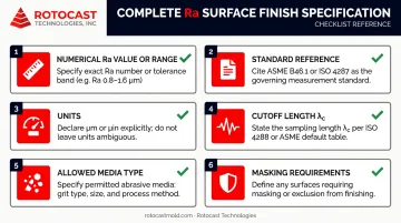
"Sandblasted" written alone on a drawing is not a surface finish specification. A complete Ra callout requires:
- Numerical Ra value or range — e.g., 2.5–4.0 µm Ra (not just "sandblasted finish")
- Standard reference — ASME B46.1 or ISO 4287
- Units — µm or µin
- Cutoff length (λc) — critical, see below
- Allowed media type — aluminum oxide, glass bead, etc.
- Any masking requirements — critical bore, sealing surfaces, parting lines
Also clarify whether you're specifying a maximum Ra (≤ X µm) or a target range (X–Y µm). Maximum Ra callouts suit adhesion applications; range callouts are needed when Ra must stay within a band — such as rotational mold interiors where a specific part texture is the goal.
Cutoff Length: The Measurement Variable Most Engineers Get Wrong
ASME B46.1 specifies cutoff lengths (λc) by Ra range:
| Ra Range | Required Cutoff (λc) | Evaluation Length |
|---|---|---|
| 0.1 to < 2.0 µm | 0.8 mm | 4.0 mm |
| 2.0 to < 10 µm | 2.5 mm | 12.5 mm |
For sandblasted aluminum targeting 1.6–6.3 µm Ra, the cutoff changes across the range. A surface measuring 1.8 µm Ra requires a 0.8 mm cutoff; a surface measuring 3.0 µm Ra requires 2.5 mm. A supplier and buyer using different cutoffs on the same part will produce different readings from an identical surface — both technically valid under the standard.
Specify the cutoff length on the drawing or purchase order to prevent this dispute.
Field Verification vs. Lab Measurement
Contact profilometers (stylus-type instruments) are the standard for Ra acceptance on blasted aluminum. Before measuring:
- Surface must be clean and dry — residual abrasive or dust inflates apparent Ra
- Stylus must traverse perpendicular to any dominant texture direction
- Confirm instrument calibration against a traceable reference standard
Surface roughness comparator plates work well for quick field screening — Elcometer's comparators provide reference grades for grit-blasted profiles — but ASME explicitly states they are not substitutes for stylus measurement in acceptance decisions. Treat them as a production floor filter for obvious outliers, not a final acceptance tool.
Consequences of Incorrect Ra
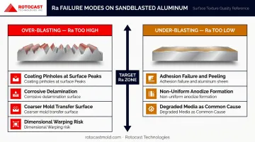
Over-Blasting: Ra Too High
Excessive Ra creates a set of functional problems beyond cosmetic roughness:
- Coating failures: Paint and powder coat fill deep valleys unevenly, leaving pinholes and voids at surface peaks where coverage is thin
- Corrosion initiation: High surface peaks under coatings correlate with increased delamination. Research on machined AA6111 aluminum confirmed a direct relationship between increasing Rz and corrosive delamination of coated surfaces
- Mold tooling: On a rotational mold interior, over-blasting produces a coarser part surface than specified — potentially causing cosmetic rejections on every part from that mold
- Dimensional risk: Thin aluminum panels can warp under excessive blast pressure, affecting part fit and assembly
Under-Blasting: Ra Too Low
Insufficient Ra generates a different set of problems:
- Adhesion failure: Without adequate anchor profile, coatings have no mechanical grip. Peeling, delamination, and disbondment follow
- Anodizing prep: Too-smooth a surface may produce non-uniform oxide layer formation
- Common cause: Degraded media (particles too fine from breakdown) or insufficient blast pressure — the Ra looks acceptable visually but doesn't measure out
Start With the Downstream Requirement
Ra is not an independent choice — derive it from what the downstream process actually requires. For rotational molds, this means working backward:
- Define the desired part surface texture — the finish your customer or application specifies
- Back-calculate the mold interior Ra that transfers that texture consistently across production
Because the mold surface transfers directly to every part produced, a Ra spec that's off by even a few microinches can mean every part out of that mold falls outside spec — and correcting it requires re-finishing the mold itself.
Frequently Asked Questions
What is the Ra finish on aluminum?
Ra (Roughness Average) is the arithmetic mean of surface height deviations measured across a defined sampling length, expressed in µm or µin. Aluminum surfaces range from mirror-polished (Ra ~0.05 µm) to heavily blasted (Ra 6.3 µm or higher), with the appropriate value driven by the downstream process requirement.
What is the surface finish of sandblasting?
Sandblasting produces a matte or satin texture. On aluminum, Ra values typically fall in the 0.8–6.3 µm (32–250 µin) range, depending on media type, grit size, and blast pressure. Glass beads produce finer, lower-Ra finishes; aluminum oxide produces coarser, higher-anchor-profile results.
What is the best abrasive for blasting aluminum?
It depends on the outcome. Aluminum oxide suits coating prep (powder coat, paint, adhesive bonding) due to its aggressive anchor profile; glass beads work better for cosmetic finishes and anodizing prep where a lower Ra and satin appearance is required. Never use steel grit on aluminum — contamination introduces corrosion risk.
How is Ra measured on a sandblasted aluminum surface?
A contact profilometer (stylus instrument) is the standard tool. Use a 0.8 mm cutoff length for Ra below 2.0 µm and 2.5 mm for Ra in the 2.0–10 µm range per ASME B46.1. Clean all residual abrasive from the surface before measuring — contamination inflates apparent Ra readings.
Does sandblasting affect dimensional tolerances on aluminum parts?
Sandblasting removes very little material — typically only a few microns — so dimensional tolerances are rarely affected for standard parts. However, thin-walled aluminum sections can warp at high blast pressures, and critical bore or sealing surfaces should be masked before blasting to protect tight tolerances.
Can the same Ra specification apply to different aluminum alloys?
Not without process validation. Alloy hardness and temper affect how the surface responds to blast energy, so parameters calibrated for 6061-T6 may not produce the same Ra on softer alloys like 1100 or 3003, or on cast alloys like A356.2. Always verify Ra on representative coupons of the actual production material before locking in a process specification.